| N/A | - Name
Specifies the actor name. This name appears in the Collaboration or Assembly tree and is the default tooltip text.
|
- Tooltip
Specifies the tooltip text that appears when you hover over the actor. The default is the actor name, but you can select a different property or meta-property, or type a text string. To type text, which itself can contain properties, select
String and use the
Tooltip string property.
Note:
By default, labels attached to an actor display the actor's tooltip text. To change this behavior, modify the label's
Text property.
|
- Tooltip string
(Available when
Tooltip is
String.) Specifies the tooltip text. Type your text, optionally with
property keywords. For geometry actors, click
 to display the
Text pane, where you can type multiple lines of text and more easily embed properties. to display the
Text pane, where you can type multiple lines of text and more easily embed properties.
See Text pane for details on property keywords and the Text pane.
|
- Stay on top
Makes the collaborative actor visible even when a geometry actor covers it.
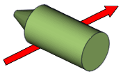 |  | | Disabled
| Enabled
|
|
- Construct Mode
Specifies how the path is drawn: -
Real path (associative paths only) - Uses a direct path.
-
Free path (non-associative paths only) - The path is a polyline you can customize.
-
Based on World Axis - Uses the world coordinate system. T
he
Axes order property defines the axis order.
-
Based on Local Axis - Uses the local coordinate system. T
he
Axes order property defines the axis order.
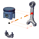 | 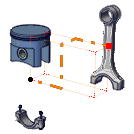 | 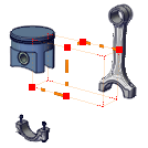 | | Real path | World Axis/
Local Axis
| Free path |
|
- Axes order
(Available when
Construct mode is
Based on World Axis or
Based on Local Axis.) Specifies the path axis order:
XYZ,
XZY,
YZX,
YXZ,
ZXY,
ZYX.
|
- Draw Full Path
(Available for associative paths when
Construct mode is
Real path.) Shows the complete path from the beginning of the animation to the end of the animation. To show the path up to the current animation time only, clear this property. The following example shows a six-second animation after three seconds:  |  | | Disabled | Enabled |
Note:
This property has no effect on associative paths from neutral.
|
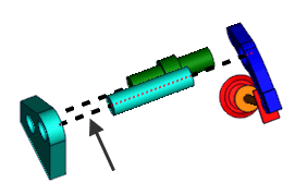
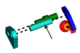
- Hidden style
-
(Available when
Stay on top is cleared.) Enables
Back line properties. A back line passes under
actors that are on top. You can define different styles for front and back
lines.
|
|
| Front Line
|
Back Line
|
|
- Opacity
Specifies the opacity, from 0 (transparent) to 255 (solid).
|
| Front line/Back line (Back line available when
Hidden style is selected)
| - Width
Specifies the line width, in millimeters.
|
- Opacity
Specifies the actor opacity (between 0 and 255).
|
- Color
Specifies the line color.
|
- Type
Specifies the line style.

| Selects a predefined style.
| | User defined | Defines a custom dashed-line style (see the
Dash pattern property).
| | Advanced | Defines a custom line style using symbols and custom spacing (see the
Symbol #
n,
Symbol size, and
Space between symbols properties).
|
|
- Dash pattern
(Available when
Type is
User defined.) Defines the line as a repeating series of dashes and spaces of the specified lengths, in millimeters. For example,
2.0 4.0 8.0 8.0 defines a 2 mm dash followed by a 4 mm space followed by an 8 mm dash followed by an 8 mm space, and then repeat.

|  | | 2.0 2.0
| 2.0 4.0 8.0 8.0
|
|
Symbol #1
Symbol #2
Symbol #3
Symbol #4
- Style
-
(Available when
Type is
Advanced.) Defines a custom line style consisting
of up to 4 different symbols.
|
|
None
|

|
Bold arrow
|

|
Medium arrow
|

|
Thin arrow
|

|
Rhombus
|

|
Round
|

|
Cross
|

|
Star
|

|
Plus
|

|
Square
|

|
Minus
|

|
Half Sinus up
|

|
Half Sinus down
|

|
Small round
|
|
- Symbol size
(Available when
Type is
Advanced.) Specifies the size of each symbol.
|
- Space between symbols
-
(Available when
Type is
Advanced.) Specifies the space between symbols as
a multiplier of
Symbol size.

|

|

|
| -0.5 (overlapping)
|
0 (touching)
|
1 (one symbol width)
|
|
| Border | - Show
Displays the border.
|
- Width
Specifies the border line width, in millimeters.
|
- Opacity
Specifies the border opacity (between 0 and 255).
|
- Color
Specifies the border color.
|
- Type
-
Specifies the border type.

|
| Extremity |
- Start
-
Specifies the extremity symbol for the line start point.

|
None
|

|
Bold arrow
|

|
Medium arrow
|

|
Thin arrow
|

|
Rhombus
|

|
Round
|

|
Cross
|

|
Arrow
|
|
- End
-
Specifies the extremity symbol for the line end point.

|
None
|

|
Bold arrow
|

|
Medium arrow
|

|
Thin arrow
|

|
Rhombus
|

|
Round
|

|
Cross
|

|
Arrow
|
|
- Size
Specifies the size of the extremity symbol (between 0.5 and 100).
|