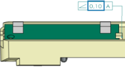
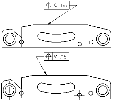
You can specify document-level drafting settings for geometric tolerances. Available for all document types.
To open this page:
With a drawing open, click Options
 (Standard
toolbar), select the Document Properties tab,
and then select .
Overall drafting standard
| Overall
drafting standard
|
Inherited from the selected Drafting Standard page
settings. |
Base geometric tolerance standard
| Base
geometric tolerance standard
|
Select a standard:
- ANSI
- ISO
- DIN
- JIS
- BSI
- GOST
- GB
|
Leader style
 Leader Style
|
Select: a style. |
 Leader Thickness
|
Select: a thickness or select
Custom Size and enter a
thickness. |
Frame style
 Frame Style
|
Sets the style for the shape
surrounding the text. |
 Frame Thickness
|
Select: a thickness or select
Custom Size and enter a
thickness. |
Text
| Font
|
Click to modify the font.
|
Decimal Separator
| Decimal Separator |
|
 |
Leader anchor
| Leader
anchor
|
Select a default anchor position:
|
 |
Leader display
| Leader display
|
Select from:
- Straight
- Bent. Inserts a horizontal bend in the
leader that is aligned with the text. Select either:
- Use
document leader length. Derives leader
length from the Annotations
page settings.
- Leader length. Lets you enter the
length of the unbent portion of the leader.
|
Material
condition
symbol
placement
| Material Condition Symbol
Placement |
Select a standard:
|
Layer
| Layer
|
Select a layer. You must
first create layers for the drawing before you can select
them for document properties.
|
You must select Per
Standard for Layer (Layer
toolbar) in the drawing view document to apply these layer settings.