You
can use pin connectors to simulate the behavior of pins in an assembly without modeling the
actual pin
geometries.
An assembly consists of multiple parts connected to each other with pins,
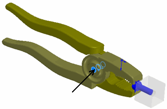
bolts, screws, or springs. Examples of assemblies with pins include laptops, scissors lifts,
pliers, and actuators. To simulate such assemblies, traditionally, you would need to create
each pin geometry and apply contact conditions between the pins and their contacting faces.
This is a computationally expensive approach.
In
applications
where
you
want to know the
effects of pins on adjacent
parts
rather
than the stress distribution
of
the pins themselves,
use
pin connectors to
simulate
the behavior of the
pins.
You can define a single pin connector attached to multiple coaxial
cylindrical
faces or
shell
edges
(maximum of
10
selections).
In the Connector-Pin PropertyManager,
for Cylindrical Faces/Edges
 , select all coaxial cylindrical faces (or
edges) that are attached to the pin (maximum of ten). The selected cylindrical faces or
circular edges can belong to one body or to several bodies.
, select all coaxial cylindrical faces (or
edges) that are attached to the pin (maximum of ten). The selected cylindrical faces or
circular edges can belong to one body or to several bodies.
When to Use Pin Connectors
 |
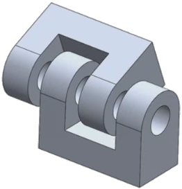
Define
one pin connector that acts as a hinge to connect the three
plates. |
 |
Define a pin connector to connect the two
cylindrical faces that rotate against each other. Allow the cylindrical faces to
rotate against the pin, but prevent them from moving axially with respect to each
other. |
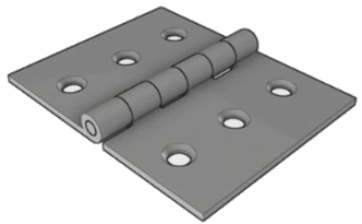 |
Define one pin connector to connect the six
cylinders of the hinged plate. |
 |
Define
a pin to connect the two rotating parts. One pin connector attaches to four
cylindrical faces. |