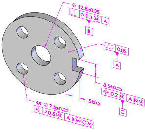
Using Auto Dimension Scheme, you can specify
one of two tolerance types, Plus and Minus or
Geometric. This option affects the tolerance types used to
control the location of bosses, cones, holes, notches, slots, and widths, as well as pockets
and profile features. With geometric tolerancing, tolerances also control the relationships
between the datum features.
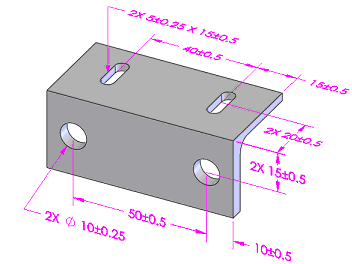
Plus and Minus Tolerancing
Features-of-size are located with linear dimensions if they are
parallel to one of the reference
features.
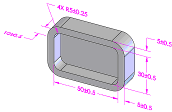
Pockets are located with linear dimensions if the wall features are
parallel to one of the reference features. The fillets, chamfers, and depth of the
pocket are dimensioned for
size.
Profile features are not
dimensioned.

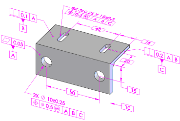
Geometric Tolerancing
Features-of-size are located with position or runout tolerances as
defined by the part type (prismatic or
turned).
Pockets are located with surface profile tolerances, including the
fillets and chamfers applied along the walls of the pocket. The depth of the pocket
is dimensioned
separately.
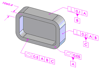
Profile features are located with surface profile
tolerances.
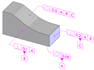
The datum selections are toleranced in order to control their
interrelationships. The following is the result where the front plane (A) is chosen
as primary, the center hole (B) as secondary, and the notch (C) as tertiary, for
controlling the 4X pattern of
holes.
