By default, CircuitWorks uses the SOLIDWORKS component origin as the
electrical component origin when exporting to CircuitWorks. You can define different origins if
needed.
For example, you might redefine the component origin if an ECAD system uses
the component origin in the ECAD file as the component insertion point. The insertion point is
normally either the center of the component, or the location of pin 1 on an integrated
circuit.
If a SOLIDWORKS assembly and its components are created from an IDF or PADS
file, CircuitWorks models the components around the origin specified in the ECAD data, so they
are likely suitable for easy import back into the same ECAD system. However, if the assembly
contains components that were modeled manually, then the origin that was convenient for
building the model but might not be ideal for the ECAD system.
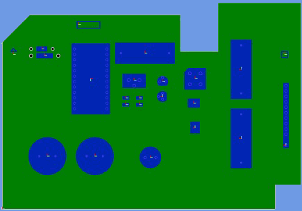
You can view component origins from the CircuitWorks
preview image. In the following illustration, CircuitWorks
shows the origins of an open IDF file. Most of the components have center origins, except the
thin rectangular component at the lower right, which has a pin-1
origin.

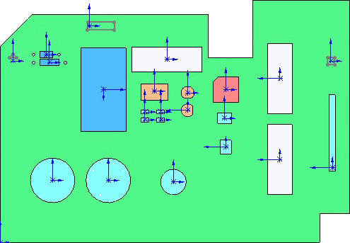
When CircuitWorks creates the SOLIDWORKS assembly from this IDF file, the
resulting assembly looks like the following in plan
view:

Note that CircuitWorks created the component models with their local origins
corresponding to their origins in the IDF file. All are center origins except the component at
the lower right.
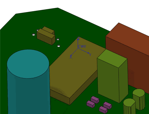
To define a new ECAD origin for the large blue IC at pin 1 rather than at the
center point, insert a user-defined coordinate system named
CWX at the
pin 1 location in the SOLIDWORKS model.

The x and y axis of
the coordinate system define the x and y ECAD axes. The z direction indicates the up
direction. The origin of the coordinate system determines the ECAD origin and its offset from
the board. See
User-Defined Coordinates for Component
Orientation.
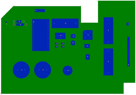
If you now export this assembly out of SOLIDWORKS and into CircuitWorks, the
preview image shows the new pin-1 origin for the IC. When saved, this new origin position is
written to the IDF
file.

The model in
the CircuitWorks Component Library now differs from the IDF data. Their shape is the same,
but their origins are different. Because CircuitWorks only models components that are not
already in the library, you must delete the existing component model from the library so
that CircuitWorks builds a new model with the new origin the next time CircuitWorks
encounters this component in an IDF file.