A bearing connector simulates the interaction between a shaft and
a housing through a bearing. To define a bearing connector, you must model the
geometries of the shaft and the housing.
You can define a bearing connector between split cylindrical faces of a
shaft, and cylindrical or spherical faces of a housing.
The surfaces of a shaft and a housing that are connected to a bearing
connector can deform relative to each other. The level of relative deformation between
the shaft and the housing surfaces depends on the user-defined connector stiffness.
Type

|
Bearing
|
|

|
For shaft: Cylindrical Face
|
Select a full cylindrical face or
concentric cylindrical faces of smaller angles adding up to 360o. This selection
corresponds to the part of the shaft resting on the bearing.
Create split lines to ensure that the
bearing connector is only defined on the proper faces of the
shaft. You can make the model excessively stiff, if you
select the entire face of the shaft.
|

|
For
housing: Cylindrical face or circular edge of shell
|
Select a cylindrical face,
spherical face, or a circular shell edge (if the housing is modeled
with shells). This selection corresponds to the part of the housing
resting on the bearing. |
| |
|
|
Connection Type
|
Distributed
|
A bearing connector modeled
with the Distributed
type connects the reference nodes of a two-node generalized
element to a group of coupling nodes on the surfaces of the
shaft and housing. One reference node (located at the centroid
of the solid shaft section that is resting on the bearing)
connects to the outer surface of the
shaft.
The second reference node (located at the
center of the housing section that is resting on the bearing)
connects to the housing internal faces. A generalized element
connects the two reference nodes, as shown in the following
image.
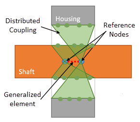
Distributed
coupling constrains the motion of the coupling nodes to the
translation and rotation of the reference node. Distributed
coupling allows the coupling nodes on the selected geometry
(shaft or housing) to move relative to each
other.
|
|
Rigid
|
A bearing connector modeled with the
Rigid type has a
similar
formulation with a Distributed type connector.
The only difference for the rigid formulation is that
individual two-node rigid elements connect the reference
nodes to the coupling nodes on the surfaces of the shaft and
housing, as shown in the following image. 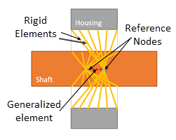 The coupling nodes on the selected geometry
(shaft or housing) do not move relative to each other.
|
|
Spring
|
A bearing connector modeled with the
Spring type is
represented with spring elements distributed radially
between the surface nodes of the shaft and the housing, as
shown in the following image. 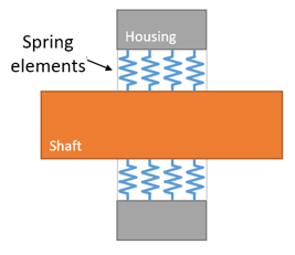 These local springs provide resistance to
off-axis rotations of the shaft.
|
Connector Stiffness
This section refers to the stiffness applied between the two
reference nodes of a generalized element and also refers to the stiffness applied to
the individual springs for the Spring type.
Each reference node of the two-node generalized element has six
degrees of freedom. You can set the lateral, axial, torsional (optional), and tilt
stiffness (optional) values of the bearing connector in this section.

|
Units
|
Specifies the required unit
system. |
| |
Rigid (infinite stiffness)
|
|
Distributed and
Rigid
Connection Type
|
Applies very high stiffness values to
the reference nodes of the generalized element.
|
|
Spring Connection Type
|
Applies very high stiffness to the
individual springs that are distributed radially between
the selected faces of the shaft and the housing.
|
The selected face of the shaft cannot translate
laterally or axially.
|
| |
Flexible
|
|
Distributed and
Rigid
Connection Type
|
Specifies finite axial and lateral
stiffnesses to the reference nodes of the generalized
element. The selected face of the shaft can translate
laterally or axially according to the defined
stiffnesses.
|
|
Spring Connection Type
|
Specifies the stiffness of the springs
that are distributed radially between the selected
cylindrical faces of the shaft and the housing.
|
You can define total stiffnesses for the lateral
and axial direction for connectors with the Distributed or Rigid type, and distributed
radial (per unit area) and distributed axial stiffnesses (per
unit area) for connectors with the Spring type.
|
 Lateral
|
Applies the lateral stiffness of the
shaft, k, which resists displacement along the direction
of the applied load. For a
Spring
connection type, the total stiffness K resisting the
lateral displacement of the cylindrical face of the
shaft (along the direction of the applied load)
relates to the radial stiffness per unit area with
the equation: K(total lateral) = 0.5 *
k(radial / unit area)
* Area
Area = diameter * height *
Pi
|
|
 Axial
Axial
|
Applies the axial stiffness, k(axial), which resists
displacement along the axis of the shaft.
|
|
 |
Tilt
Stiffness |
Tilt stiffness is available for
the Distributed and
Rigid connection type. Applies a tilt stiffness to the reference nodes
of the generalized two-node element to resist the bending of the
shaft.
To recreate the Allow Self-alignment option,
which was available in releases before 2024, set the Tilt stiffness to
zero.
|
| |
Stabilize shaft rotation
|
Select this option to prevent
rotational instability of the shaft (caused by torsion) that can
lead to numerical singularities. You can accept the default
Automatic option or
apply a user-defined torsional stiffness. The
Automatic option
applies a minimal torsional stiffness to the shaft's cylindrical
face that provides circumferential resistance against
torsion.
This prevents the shaft from
rotating freely about its axis and eliminates
instability.
|
Symbol Settings
| |
Edit Color
|
Select a color for the
symbols. |

|
Symbol size
|
Set the size of the symbols.
|
| |
Show preview
|
Toggles the display of the
connector symbols in the graphics area. |
Notes
- Available for static, frequency, linear dynamic, and
buckling studies. Not available for composite shells.
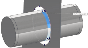
- Use the Split Line
tool to define the cylindrical faces for the shaft that are resting on the
bearing. For example, use the Split
Line tool to create the following highlighted face to apply
a bearing connector.
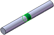
- To define a bearing connector between a solid shaft surface
and a circular shell edge housing, set the Connection Type to Rigid, as shown in the example below.
-
When to use a Bearing Connector A
bearing fixture assumes that the components supporting the shaft are much
more rigid than the shaft and can be considered as fixed to the ground. When
this assumption is not valid and the flexibility of the supporting parts
must be included, you should use a bearing connector formulation to simulate
the connection. You need to model not only the shaft but also the housing.
In the example shown below, the bearing connectors are
defined between the cylindrical split faces of the shaft and the
spherical faces of the housing.