The
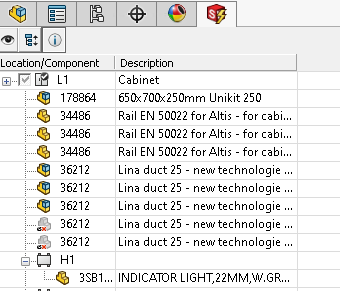
list of available components appears in the dockable
panel. This list
specifies the components that you can insert into the open 3D assembly.
When you insert the
component, the software validates the component and updates the shortcut menu.
Right-click a component to insert it.
Insert
SOLIDWORKS Electrical 3D determines if there is a 3D file associated with the
manufacturer part (from ). If nothing is defined, the software searches SOLIDWORKS\sldprt (first, in the project folder and
after in the software folder), for a part with the same name as the manufacturer
part reference. If the software does not find a part, the software searches the
classification node of the manufacturer part to see if a file is defined, then goes
through all the parent nodes and determines if a 3D part is defined. Otherwise, the
software uses the default EW_DEFAULT.SLDPRT.
The assembly scale changes during insertion (in X, Y, and Z) to comply with the
dimensions stored in the manufacturer part.
Insert As
You can use
Insert As for specific
components such as cabinets, ducts, or rails. Select in the menu the element type.
The software inserts a specific 3D part using the manufacturer part dimensions. If
you double-click the manufacturer part, the software uses the manufacturer part
classification to select the 3D part to insert. The 3D parts are:
- EW_CABINET.SLDASM to
insert a cabinet.
- EW_DUCT_H.SLDASM to
insert a horizontal duct.
- EW_DUCT_V.SLDASM to
insert a vertical duct.
- EW_RAIL_H.SLDPRT to
insert a horizontal rail.
- EW_RAIL_V.SLDPRT to
insert a vertical rail.
You can replace the above files with others.
Insert from File
You can insert a user-defined component (this opens a dialog box where you can
select a preferred SOLIDWORKS file). As with Insert
As, the file scale changes to insert it with the dimensions of the
manufacturer part. Each component type has its tool for insertion. For example, you
cannot insert a rail using the cabinet insertion tool.
Multi-Insertion
If you select several components, you can use the Insertion order dialog box to manage the order of component
insertion. Similarly, to insert a component with several associated manufacturer
parts, you can manage the order of the component insertion.
- Multiple insertion.
Specifies the side used to insert the second and the next components.
- Spacing. Specifies
the space between two 3D parts.
Terminal strip insertion also uses this process.
Insert Cabinet
Right-click a cabinet and select Insert as
cabinet
 . If you have a SOLIDWORKS cabinet
representation file, select Insert from file.
If you do not have an associated file, click Insert. SOLIDWORKS Electrical 3D uses the generic file and
generates a cabinet that matches the manufacturer part dimensions.
. If you have a SOLIDWORKS cabinet
representation file, select Insert from file.
If you do not have an associated file, click Insert. SOLIDWORKS Electrical 3D uses the generic file and
generates a cabinet that matches the manufacturer part dimensions.
Insert Rail or Duct
Right-click a rail (or duct) and select Insert as horizontal (vertical) rail (duct)

 .
.
The software manages rails and ducts as cabinet accessories. To insert a rail,
use Insert, Insert
from file or Insert as vertical
rail or Insert as horizontal
rail from the shortcut menu.
Ducts and rails have saved mates to place on the base of the cabinet. Click
 to validate the mate while
inserting.
to validate the mate while
inserting.
To assemble ducts, click .
During insertion, the panel automatically updates to define the length.
Define Length
Length. Specifies the rail or duct
length.
Click to
validate.
Insert Component
To insert a component:
- Right-click a component and select Insert
 .
.
- To insert components, use Insert or Insert from
file.
The component is displayed in the
graphics area.
- Click a point to insert the component.
According to the mate references created on the 3D assembly, if you
click a point on a rail, the assembly is automatically centered on the point.
Insert Terminal Strips
There are two tools for inserting terminals. You can insert each
terminal individually, or you can insert the entire terminal
strip.
To insert terminal strips:
- Right-click a terminal strip and select Insert terminals
.
- To insert the terminals individually, click Insert terminals from the terminal reference
shortcut menu.
- To insert the entire terminal strip, click Insert terminals in the shortcut menu of the
terminal strip.
- Click the insertion point to place the first terminal.
The dockable panel changes to insertion options.
Insert Terminals
Insert terminals. Indicates the
insertion direction (right or left) of the other terminals.
Spacing. Specifies the distance between
two terminals.
Insert base manufacturer part only Does
not insert the terminal trip accessories or auxiliaries.