This topic explains the parameters in the default IEC configuration for
PLC drawings.
General
| Name |
Description |
| General |
|
| Name |
The name of the PLC drawing configuration file. |
| Description |
A description in all languages supported by the app. |
Size
| Name |
Description |
| General |
|
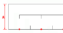
| Orientation |
The direction of the module drawing.
- Horizontal: Inserts the module at the top or bottom of the
drawing.
- Vertical: Inserts the module on the right or the left.
|
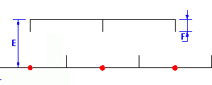
| Size |
All numeric values use the unit system specified in
the electrical project configuration. |
| A Symbol height |
The height of the module.
|
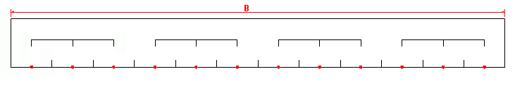
| B Maximum length of symbol in a
drawing |
The height of the module.
|
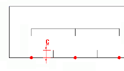
| Channels |
|
| C Channel separator
height |
The length of the vertical line separating 2 PLC
channels.
|
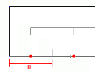
| D Channel width |
The width of the channel.
|
| Combs |
The comb is the graphic element grouping
channels. |
| E Comb height |
The distance between the bottom of the module and the
horizontal line of the comb. |
| F Comb tooth height |
The height of the vertical line of the comb.
|
| Name |
Description |
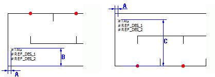
| Information (Left) |
These attributes have a left justification.
|
| A X coordinate |
The distance between the vertical line of the module
and the insertion point of attributes. |
| B Y for bottom symbol |
The distance between the horizontal line of the module
and the insertion point of attributes for a module symbol inserted at
the bottom of the drawing. |
| C Y for top symbol |
The distance between the horizontal line of the module
and the insertion point of attributes for a module symbol inserted at
the top of the drawing. |
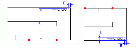
| Information (Right) |
These attributes have a right justification.
|
| D X coordinate |
The distance between the vertical line of the module
and the insertion point of attributes. |
| E Y for bottom symbol |
The distance between the horizontal line of the module
and the insertion point of attributes for a module symbol inserted at
the bottom of the drawing. |
| F Y for top symbol |
The distance between the horizontal line of the module
and the insertion point of attributes for a module symbol inserted at
the top of the drawing. |
Layout
Manages the PLC module drawing layout settings. Settings in the General section are
available only for vertical representations of the module, specified on the
Size tab.
| Name |
Description |
| General |
|
| Options |
Layout options for inserted symbols:
- One symbol per page
- One symbol per column
- Custom
These options are available only if you select
Vertical orientation in the
Size tab.
|
| Column size |
The column size of the column. The preview displays a
vertical line to show this value. This option is
available only if you select the One symbol per
column layout option.
|
| Symbol insertion point |
A description in all languages supported by the
app. |
| A X coordinate |
The X coordinate corresponding to the insertion point
of the module. |
| B Y for top symbol |
The Y coordinate corresponding to the insertion point
of the module when the app draws the module at the top of the drawing.
|
| C Y for bottom symbol |
The Y coordinate corresponding to the insertion point
of the module when the app draws the module at the bottom of the
drawing. |
Connection Point
Defines the symbol used to propagate the terminal number. This symbol must contain
the attribute
#P_TAG_0.
 Opens
the symbol selector.
Opens
the symbol selector. Removes
the symbol.
Removes
the symbol. Opens
the symbol editor.
Opens
the symbol editor.
| Name |
Description |
| Symbol on top |
|
| Symbol on bottom |
|
Circuits
Defines the symbols and macros associated with a type of circuit for a graphical
representation at the top or bottom of the drawing. The app examines the module
circuits in the order that they appear in PLC management. The module circuit is
compared with the circuits in the configuration list. As soon as the circuits match,
the app saves the setting you have selected, and uses it to insert the module.
| Name |
Description |
| Circuit type |
Specifies the type of circuit. |
| Direction |
Specifies the direction of module insertion:
- Top: The app inserts the module in the upper part of the
drawing.
- Bottom: The app inserts the module in the lower part of the
drawing.
- Undefined: The app does not insert the module. The app continues
to the next circuits until it finds one defined as top or
bottom.
|
| Delete circuit type
association |
Dissociates a symbol or macro from the circuit, or
deletes the existing associations. |
| PLC channel pattern symbols |
Selects the symbols representing the inside of the
module for insertion in the top or bottom part of the drawing. These
settings are associated with the selected circuit. |
| Macro connected to channels |
Automatically generates the diagram connected to the
module for insertion in the top or bottom part of the drawing. You can
associate a macro with each type of circuit. |
File Data
Defines the parameters for the automatic generation of information to transfer into
the properties of the terminal stripPLC drawing. Clicking the right-hand column
allows you to open Formula management.
| Name |
Description |
| Description |
Lets you define the parameters for the automatic generation of
data to transfer into the description of the terminal strip drawing. |
| User data/Translatable data |
Lets you specify the parameters for the automatic generation of
data to transfer into the user data of the terminal strip drawing. |