SOLIDWORKS
You can specify which configuration to convert and configure the import
options.
| Command Name | Description |
|---|
| Select the configuration to
open | From the list, select configurations to save with
the Composer file. Select current
configuration. Saves the active configuration
with the Composer file. Select all
configurations. Saves all configurations with
the Composer file. Select following
configurations. Saves the selected
configurations with the Composer file. Select one or more
configurations. | | Import SOLIDWORKS
appearance | Imports all appearances in SOLIDWORKS files. You can also specify
this option as follows: - In Composer, click . Under INPUT - IMPORT,
enable IOSWImportAppearance.
- In Composer Sync, at the bottom of the window, click . Under INPUT - IMPORT,
enable Batch.IOSWImportAppearance to
enable batch import of appearances.
- In the SOLIDWORKS software, click . Under File Format,
select SMG, and select
Export SOLIDWORKS appearance.
| | Import SOLIDWORKS
decals | Imports decals from SOLIDWORKS files to Composer files. You can also specify
this option as follows:
- In Composer, click . Under INPUT - IMPORT,
select IOSWImportDecals.
- In Composer Sync, at the bottom of the window, click . Under INPUT - IMPORT,
select Batch.IOSWImportDecals to
enable batch import of decals.
- In the SOLIDWORKS software, click . Under File Format,
select SMG, and select
Export SOLIDWORKS decals.
Note:
The following apply:
- The Import SOLIDWORKS decals
check box is independent of the
Import SOLIDWORKS appearance
check box. If you clear Import SOLIDWORKS
appearance and select Import
SOLIDWORKS decals, then the color and
texture of the SOLIDWORKS file is not imported. Only
decals are imported to the Composer file.
- The appearance of decals in Composer should be same as
that in SOLIDWORKS. The properties of decals in
SOLIDWORKS like size, position, mapping, and masking are
supported in Composer.
- If you import a SOLIDWORKS file with multiple
configurations, then decals specific to each
configuration are imported.
- Composer supports a maximum of four decals per
face.
To render decals correctly in SOLIDWORKS Composer:
- Use OpenGL version >= 1.3
- In , under Graphics,
select Enable 3D OpenGL hardware
acceleration.
| | Import SOLIDWORKS BOM | Imports part and assembly BOMs in SOLIDWORKS
files. After import, you can access and edit all the BOM properties
in Composer. You can also specify this option as follows: - In Composer, click . Under INPUT - IMPORT,
enable IOSWImportBOM.
- In Composer Sync, at the bottom of the window, click . Under INPUT - IMPORT,
enable Batch.IOSWImportBOM to enable
batch import of BOMs.
- In the SOLIDWORKS software, click . Under File Format,
select SMG, and select
Export SOLIDWORKS BOM.
| | Import SOLIDWORKS Explode Views and Saved
Views | Imports all exploded, saved, and named views in SOLIDWORKS files.
You can also specify this option as follows: - In Composer, click . Under INPUT - IMPORT,
enable IOSWImportExplodeViews.
- In Composer Sync, at the bottom of the window, click . Under INPUT - IMPORT,
enable Batch.IOSWImportExplodeViews
to enable batch import of exploded, saved, and named views.
- In the SOLIDWORKS software, click . Under File Format,
select SMG, and select
Export SOLIDWORKS Exploded views and Saved
Views.
| | Import SOLIDWORKS assembly envelope | Imports all the SOLIDWORKS assembly envelopes. You can also
specify this option as follows: - In Composer, click . Under INPUT - IMPORT,
enable IOSWImportEnvelope.
- In Composer Sync, at the bottom of the window, click . Under INPUT - IMPORT,
enable Batch.IOSWImportEnvelope to
enable batch import of envelope geometry.
- In the SOLIDWORKS software, click . Under File Format,
select SMG, and select
Export SOLIDWORKS assembly
envelope.
|
Import
You can configure Import options.
| Command Name
|
Description
|
| Import profile
|
Sets import options as recommended for the selected
format.
Notes:
- Selecting a profile makes all import options read-only.
To override profile settings, select
Custom.
- When you revisit the Input page, the profile reverts to
Custom but the import option
settings are retained.
- You cannot redefine or create new import profiles.
- Import profiles are not available on the Sync Import
Options page. Set import options manually as needed.
|
| Merge file into one actor per part
|
Imports parts, including multibody parts, as single
actors. To load multibody parts as individual actors, clear this option.
Notes:
- For SOLIDWORKS models, this option merges all part
geometry and creates single nodes in the Composer assembly tree that are both
part and geometry nodes. For other CAD formats, this option merges part
geometry but creates part nodes with geometry nodes.
|
| Import instance names
|
Adds the instance names after the part name: #PN# (#IN#).
#PN# and #IN# are also added as meta-properties so you can add annotations
linked to these meta-properties.
Note:
When importing 3DXML files containing 3D shapes that are
aggregated directly under the root node of the product reference, make sure
that you select this option if you want to import both the name of the 3D shape
reference, and the name of the 3D shape instance.
|
| Import meta-properties
|
Imports user-defined attributes such as part number (P/N), designation, and revision
number. Meta-properties appear as user properties of the string type
in the Properties pane. Note:
Meta-properties can be imported from 3DXML (*.3dxml), Pro/E Creo
(*.prt, *.asm), and STEP (*.stp, *.step) files.
|
| Overload assembly tree
names
|
Uses the text value associated to a given
meta-property (instead of the default Actor.Name property) to display actor
names in the assembly tree.
In the text box, the V_Name value is entered by default.
This displays the value associated to the Meta.V_Name meta-property. Enter the
name of another meta-property if the default one does not suit your needs.
Notes:
- This option is available only if
Import meta-properties is
selected.
- In order for this option to be taken into
account, you need to close and then re-open the current Composer document, or
perform an operation that will refresh the Assembly Tree.
- If the meta-property is a
configuration specific property, then add the suffix
_cfg to the property name.
|
| Import as bodies
|
Imports parts as solid bodies. To import parts as
individual faces, clear this option and clear
Merge file into one actor per part. If
you select
Merge file into one actor per part, it
does not matter what you select for
Import as bodies; multibody parts import
as single bodies.
|
| Import area, volumes, inertia axes
|
Displays surface and volume information from CAD models as
meta-properties on the assembly level. This option is useful only for
translation of CAD files into Composer format.
|
| Import points
|
Imports point geometry.
|
| Import curves
|
Imports curve geometry (curves, wires, wireframes).
|
| Import free faces
|
Imports surface bodies (construction faces).
|
| Import hidden components (no show)
|
Imports and displays hidden parts in assemblies and bodies
in multibody parts. The hidden components are stored in a selection set.
Note:
Suppressed components are never imported.
|
| Import coordinate systems
|
Imports coordinate systems.
Notes:
- Coordinate systems are not imported when
Merge file into one actor per
part is selected.
- Use this option with caution. Models can have large
numbers of coordinate systems.
|
| Import
textures
|
Imports textures, including UV textures, on actor faces.
Notes:
- Composer can import one texture per face
(single-channel). If geometry has a multi-channel texture, Composer imports the
first channel only.
- Changing the
property of an actor with imported textures
loses texturing-by-face. The specified texture is applied to all actor faces.
- You can apply texture properties such as
Environment effect,
Blending, and
Transparency to imported textures.
- The
property is set to
Imported texture for actors with
imported textures. Changing the projection mode loses the imported texture.
- The
Update Composer Document command
updates UV coordinates of imported textures. Texture property changes made in
Composer, such as
Map path and
Scale, are retained.
|
| Import PMI | Imports Product Manufacturing Information (PMI) data from
SOLIDWORKS models. Composer imports: - Dimensions
- Datums
- Tolerances for dimensions
- Geometric tolerances
- Special symbols such as diameters and degrees
- Surface finishes
To modify the PMI colors during import, select
Overwrite color and choose a color,
which is applied to all the imported PMI data. After you import
the PMI data into a *.smg file, the PMI
data is visible in Composer Player.
Composer stores the PMI data in the PMI Data
(SOLIDWORKS) folder under a root node on the
Assembly tab. Select or clear check
boxes to hide or show the PMI data.
Composer imports view-based data such as annotation views from
SOLIDWORKS and 3D views from SOLIDWORKS MBD. Composer stores
these views in the PMI Views (SOLIDWORKS)
folder under a root node on the
Assembly tab in Composer. The
3D Views and Annotation
Views subfolders contain these specific
categories of imported views.
Note:
After you import the PMI data into a
*.smg file, the PMI data is visible
in Composer Player. Composer Sync also imports PMI data from
SOLIDWORKS models into *.smg files. To enable this functionality from the SOLIDWORKS software,
click and select Export PMI.
|
Refinement
Refinement settings determine how Composer tessellates (meshes)
the model, which affects model accuracy.
Set these options to achieve the best compromise between accuracy and file
size.
| Command Name
|
Description
|
| Relative
|
Specifies the triangulation method:
-
Chordal error - All geometry has the
same chordal error. Chordal error is the distance between the triangles that
define the geometry in Composer and the edges of the original geometry. When
you move the slider to
high quality, you decrease the chordal
error and increase the quality of the assembly.
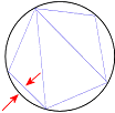
In this image, the black circle is the original geometry.
The blue triangles define the geometry in Composer. The chordal error is the
distance represented by the red arrows.

-
Normal deviation - All geometry has
the same normal deviation. Normal deviation is the angle between the normals of
the edges that define the triangular geometry of Composer. When you move the
slider to
high quality, you decrease the normal
deviation and increase the quality of the assembly.
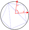
In the image, the black circle is the original geometry.
The blue triangles define the geometry in Composer. The normal deviation is the
angle between the red arrows.

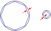
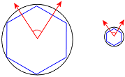
The difference between these two triangulation methods is
visible for scenes containing geometry of various sizes. Consider an assembly
of one very large cylinder and one very small cylinder.
With
Chordal error, because the chordal error
is constant, the polygon inscribing the large cylinder has many more sides.
This results in the geometry of the large cylinder looking better than the
small cylinder.

With
Normal deviation, because the normal
deviation is constant, the polygons inscribing both cylinders have the same
number of sides. This results in the geometry of the small cylinder looking
better than the large cylinder.

You can optimize the geometry degradation by moving the slider
between
high quality (for optimum triangulation
quality),
medium, and
low quality.
|
| Absolute (Advanced users only, use
carefully)
|
Defines the triangulation approximations.
You can set these three parameters independently. When you set
more than one, their effects are combined.
For each parameter, specify values that define the maximum
limits.
|
| Enable auto repair (healing is time
intensive)
|
Checks for missing triangles, incorrect holes in the mesh,
extra faces, and other discontinuity issues, and attempts to repair problems by
adding triangles. This option degrades import speed, so use only when
tessellation is poor. To import files without checking for incorrect geometry,
clear this option.
|
|