Stress linearization separates the bending and membrane stress components
from the actual stress distribution observed through the thickness of a wall in a sectional
stress plot of a pressure vessel study.
The methodology of stress linearization is according to the American Society
of Mechanical Engineers (ASME) International Boiler and Pressure Vessel Code
ASME BPVC-VIII.2-2017. The functionality is used for solid meshes only. For
shells, you can plot and list membrane and bending stresses separately.
Stress linearization provides an idealization of the actual stress variation through
a wall thickness. A membrane stress component is constant through the thickness,
whereas a bending stress component varies linearly through the thickness. A
non-linearized stress component is referenced as the Peak stress.
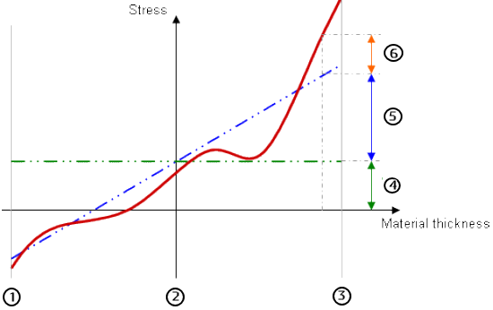
| 1 |
Inner wall boundary |
| 2 |
Midplane |
| 3 |
Outer wall boundary |
| 4 |
Membrane stress component (green dotted line
denotes membrane stress) |
| 5 |
Bending stress component (blue dotted line denotes
bending + membrane stress) |
| 6 |
Peak stress, non linearized stress component (red
solid line denotes actual stress) |