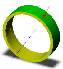
You can use an axis as a reference to apply restraints. You can prescribe the translations in the radial, circumferential, and axial directions. For shells and beams, you can prescribe rotations in reference to these directions.
The angle (θ) specified for the circumferential translation is used to calculate the actual translation (v) at each node from the formula: v = r. θ where r is the distance from the node to the reference axis.
The following table summarizes the attributes of this restraint type:
| Attribute
|
Value
|
|---|
| Possible DOFs for solids
|
3 translations
|
| Possible DOFs for shells and beams
|
3 translations and 3 rotations
|
| Possible DOFs for trusses
|
3 translations
|
| 3D symbol
|
 |
 |
| translation
|
rotation
|
|
| Selectable entities
|
Vertices, edges, faces and beam joints
|
| Translations
|
 Radial displacement Radial displacement
 Circumferential displacement Circumferential displacement
 Axial displacement Axial displacement
|
| Rotations (for shells and beams only)
|
 About radial direction About radial direction
 About circumferential direction About circumferential direction
 About axial direction About axial direction
|
Example
 |
|
| The selected face of the cylindrical hole can rotate about or move along the reference axis shown in the figure. Thick red arrows represent allowable motions.
|
|
 |
 |
 |
| Fig. 1
|
Fig. 2
|
Fig. 3
|
| Consider fitting the ring in Fig. (1) inside the ring in Fig. (2). The inner ring (Fig. 1) has an outer diameter of 18.2 cm and is made of an elastic material. The outer ring (Fig. 2) has an inner diameter of 18 cm and is made of a rigid material. To fit the inner ring into the outer ring (Fig. 3), assign a radial displacement on the selected outer face of the inner ring of -0.1 cm with respect to the reference axis.
|