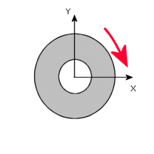
Description
A circular plate with a center hole is fixed along the inner edge. The outer edge of the plate is subjected to bending by a moment M = 10 in-lb/in. Determine the maximum deflection and the maximum slope of the plate. The plate thickness is 0.25" and the outer and inner radii of the plate are 30" and 10" respectively. Due to symmetry of the problem, a 10º wedge is modeled. The applied moment is equivalent to applying a moment of 52.359 lb-in per 10º segment.

File Name
Browse to drive
letter:\Users\Public\Public Documents\SOLIDWORKS\SOLIDWORKS
version\samples\Simulation
Examples\Verification\Static_9.SLDPRT and open the
file.
Shell Parameters
Shell thickness = 0.25 in - Thin formulation.
Meshing Parameters
Use a Global Size of 1 in.
Material Properties
Modulus of elasticity = 3 X 10⁷ psi, Poisson's ratio = 0.3.
Results
| |
Theory
|
SOLIDWORKS Simulation
|
| Maximum deflection (UZ), inch |
0.04906 |
0.04786 |
| Maximum rotation (RY), rad |
0.0045089 |
0.004519 |
Analytical Solution
D = ( E * h3) / ( 12* (1- v2) )
C1 = ( 2 * rout2 * M ) / D * ( rout2 * (1+ v ) + rin2 * (1 - v ) )
C2 = - (rout2 * rin2 * M ) / D * ( rout2 * (1+ v ) + rin2 * (1 - v ) )
Maximum rotation: RY = C1* x / 2 + C2 / x , for x = rout
Maximum deflection: UZ = C1*( (rout2 - x2) / 4 - C2 * log ( x / rout ) ), for x = rin
where:
-
E: Modulus of elasticity
- v: Poisson's ratio
-
h: Plate thickness
- rin: Inner radius
- rout: Outer radius
- M: Bending moment per unit length
- x: Radial distance
Reference
Timoshenko, S., “Strength of Materials, Part II, Advanced Theory and Problems,” 3rd Edition, D. Van Nostrand Co., Inc., New York, l956.