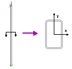
Description
A column of length 120" is subjected to a compressive normal force. The cross section of the column is an ISO rectangular tube of size: 50 x 30 x 26. Calculate the buckling load for various support conditions.

File Name
Browse to drive
letter:\Users\Public\Public Documents\SOLIDWORKS\SOLIDWORKS
version\samples\Simulation
Examples\Verification\Buckling_6.SLDPRT and open the
file.
Material Properties
Modulus of elasticity = 3X10⁷ psi, Poisson's ratio = 0.3.
Column Properties
ISO rectangular tube of size: 50 x 30 x 26. Cross sectional area: 0.58 in2; Moments of Inertia: Ix = 0.2792 in4, Iy = 0.1247 in4.
Column Restraints
Four cases are considered for the end restraints:
- Pinned - Pinned
- Fixed - Free
- Fixed - Fixed
- Fixed - Pinned
At the joint where the force is applied, the translational degree of freedom in the direction of the force is released.
Results
| Buckling Load (lb) |
Theory |
SOLIDWORKS Simulation |
| (a)
Pinned - Pinned
|
2,564 |
2,563.9 |
| (b)
Fixed - Free |
641 |
640.96 |
| (c)
Fixed - Fixed |
10,256 |
10,255 |
| (d)
Fixed - Pinned |
5,246 |
5,245 |
- (a) Pinned - pinned column: Pcr = π2E I / L2
- (b) Fixed - free column: Pcr = π2E I / 4 L2
- (c) Fixed - fixed column: Pcr = 4 π2E I / L2
- (d) Fixed - pinned column: Pcr = 2.046 π2E I / L2
where:
- Pcr = Critical (buckling) load
- E = Modulus of elasticity
- I = Smallest moment of inertia of the column's cross section
- L = Total length of the column
The critical load from SOLIDWORKS Simulation
is calculated as:
Pcr = (Applied force)*(Buckling load factor)
Reference
Gere & Timoshenko, “Mechanics of Materials”, PWS Publishing Company, Boston, MA, pp 755.