Description
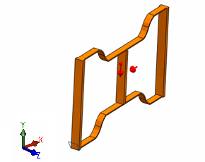
The edge of a
motor vehicle frame
traveling
at a velocity of 13.89 m/sec hits a rigid target. Compute the deformed shape of the
frame at t = 9 ms after the initial impact.

The black arrow points to the edge
that initially touches the rigid target. The rigid target is inclined at an angle of
30° with the YZ plane.
File Name
Browse to
drive letter:\Users\Public\Public
Documents\SOLIDWORKS\SOLIDWORKS
version\samples\Simulation
Examples\Verification\Motor_Frame.SLDPRT and open the
file.
Meshing Parameters
Use a Standard mesher with Global Size of 12 mm.
Material properties
Elastic perfectly plastic with:
- Elastic modulus = 213.28 GPa
- Poisson's ratio = 0.3
- Yield stress = 221.2 MPa
- Density = 7850 kg/m3
Setup Parameters
- Initial velocity of frame = 13.89 m/s
- Acceleration due to gravity = 9.81 m/s2
Results
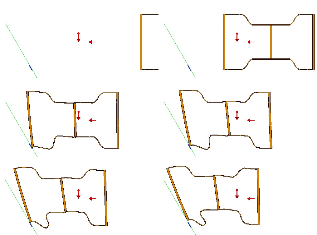
The resultant displacement (mm) plot from Simulation is shown at t =
9ms after the initial impact.
The program takes about 40 minutes to simulate up to 9 ms after
initial impact.

An animation of the crash test is shown.
Click this animation to play it or to reset it.

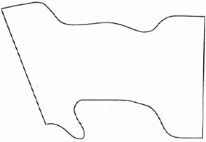
The deformed shape of the frame boundary from experimental crash test
(Volkswagenwerk) is shown at time (t) = 9ms after initial impact.

The deformation plots showed good accuracy when compared with results
from ABAQUS at time (t) = 1.7 ms and 5.9 ms (courtesy, DS Simulia Corp.).
Reference
Moldenhauer, H., “Oblique Impact of a Motor Vehicle (Crash simulation with the ABAQUS program),” Control Data Corporation, Frankfurt, W. Germany, July 1980.