Description
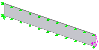
A cantilever beam of length 40'', depth 4'', and thickness 0.3'' is subjected to an end moment of 6000 in-lb for a total time duration of 200hr. Calculate the variation of the bending stress across the depth of the beam after a steady state is reached.

File Name
Browse to drive
letter:\Users\Public\Public Documents\SOLIDWORKS\SOLIDWORKS
version\samples\Simulation
Examples\Verification\Nonlinear_Static_15.SLDPRT and open the
file.
Meshing Parameters
Use a Global size of 0.727".
Mesh Control
Applied to the two vertical end faces with element size 0.25.
Material Model
Linear elastic isotropic with creep effect.
Material Properties
Modulus of elasticity = 30 x 106 psi, Poisson's ratio = 0.3, Equation of state for creep: εc = 6.4E-18 σ3.15 t (t: current real time in hr).
- Creep constant 1: 1.439e-33
- Creep constant 2: 3.15
- Creep constant 3: 1.0
The units of the creep constant 1 must entered in the SI unit system. The conversion factor is calculated as:
factor = (4.448 (N) / 0.0254^2 (m2) ) ^ creep constant 2 * (3600 sec)^ creep constant 3
Creep constant 1 = (1 / factor)* 6.4E-18 = 1.439E-33
Restraints and Loads
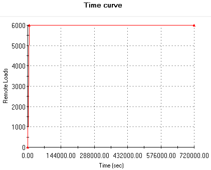
One support edge is restrained in the vertical direction. One lateral, and one longitudinal face is restrained in the normal direction. The end moment of 6000 lb-in increases linearly from 0 - 7200 sec, and is constant from 7200 - 720000 sec as follows.

Results
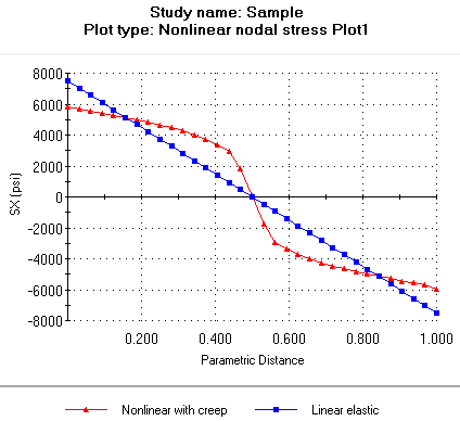
The nonlinear distribution of the normal stress across the beam's depth (support edge) due to the creep phenomenon is in good agreement with analytical results. The distribution of the normal stress from linear elastic analysis is added for comparison.

For more information on how to edit plots, see the Help in the Edge Plot window. The linear elastic graph was added with the options available in the ChartGroups tab under Options, Properties.
Reference
Mark D.Synder. Klaus-Jurgen Bathe, "Formulation and Numerical Solution of Thermo-Elastic-Plastic and Creep problems," Report 8448-3, 1977.