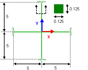
Determine the natural frequencies of a simply supported cross frame with
four beams. Consider modes in the XY plane only. The frame is 10 m x 10 m and each beam has a
square section of side 0.125 m. All dimensions are in m.

|
File Name
|
Open drive
letter:\Users\Public\Public Documents\SOLIDWORKS\SOLIDWORKS
version\samples\Simulation
Examples\Verification\NAFEMS_Freq_Test1.SLDPRT.
|
|
Mesh Type
|
Beam mesh. Use the standard mesh size.
|
|
Material Properties
|
- Modulus of elasticity (E)
= 2 x 10¹¹ N/m2
- Mass density (ρ) = 8,000
Kg/m3
- Poisson's ratio (ν) =
0.3
|
|
Restraints
|
The four end joints are simply-supported and constrained from
out-of-plane rotations. The center node is constrained in the normal direction and from
out-of-plane rotations.
|
Reference
NAFEMS, Publication R0015, The International
Association for the Engineering Analysis Community, "Selected Benchmarks for Natural
Frequency Analysis", Ref -R0015, Issue 2, Test 1, 1987.