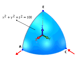
Calculate the X displacement at point A of the hemisphere due to
concentrated radial loads of magnitude 2 KN applied outwards at point A and inwards at point C.
The sphere has a radius of 10 m.
|
File Name
|
Open drive
letter:\Users\Public\Public Documents\SOLIDWORKS\SOLIDWORKS
version\samples\Simulation
Examples\Verification\NAFEMS_IC18.SLDPRT.
|
|
Shell Parameters
|
Shell thickness = 0.04 m - Thin shell formulation
|
|
Material Properties
|
- Modulus of elasticity =
68.25 X 10³ MPa
- Poisson's ratio (ν) =
0.3
|
|
Modeling Hints
|
Due to symmetry, model only a quarter of the hemisphere.
|
Results
| Component |
Reference |
SOLIDWORKS Simulation |
| UX displacement at point A |
0.185 m |
0.1847 m |
Reference
NAFEMS Publication P07, The International Association for the Engineering
Analysis Community, "Linear Statics Benchmarks VOL. 1," D. Hitchings, A. Kamoulakos, G.A.
Davies, VOL. 1, October, 1987.