Next, you define a fixture to prevent the nut from moving vertically, and apply a load to the top edge of the bolt shank.
- Do one of the following to define a fixture:
- Click the down arrow on Fixtures
Advisor
 (Simulation
CommandManager) and select Roller/Slider.
(Simulation
CommandManager) and select Roller/Slider.
- Right-click Fixtures in the study tree and select Roller/Slider.
-
In the PropertyManager, for Straight Edges
for Fixture
 ,
select the edge of the bolt and the top edge of the nut as shown.
,
select the edge of the bolt and the top edge of the nut as shown.
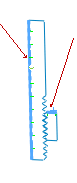
By selecting the vertical edge of the bolt and the horizontal edge
of the nut, you prevent the nut from moving along the vertical direction when the force
is applied.
-
Click
 .
.
- Do one of the following to apply an external force:
- Click the down arrow on External
Loads
 (Simulation
CommandManager) and select Force
(Simulation
CommandManager) and select Force
 .
.
- Right-click External Loads in the Simulation study tree and select Force .
-
In the PropertyManager, define the load:
-
Under Force/Torque, for
Faces and Shell Edges for Normal Force
 ,
select the top edge of the 2D bolt.
,
select the top edge of the 2D bolt.
- Select Selected direction.
- For Face, Edge, Plane, Axis for Direction
 , select Plane1 from the flyout FeatureManager design tree.
-
For Unit
 ,
select English (IPS).
,
select English (IPS).
-
Under
Force,
select Along Plane Dir 2
 and enter 3000 lbf.
This force acts on the circular face of the bolt shank.
-
Click
.