When the analysis completes, you check the FOS of connectors to examine
their pass/no pass status.
-
Right-click Results
 and select Define Pin/Bolt Check Plot.
-
Click
 .
.
The Pin/Bolt Check window displays
the safety status of all bolt connectors.
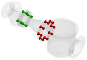
The Needs Attention folder lists
eight connectors with a resultant load safety ratio smaller than the user-defined safety
factor (2). The connectors appear red in the graphics area.
You may need to resize these connectors to pass the safety
check.
The OK folder lists four
connectors with a resultant load safety ratio larger than the user-defined safety
factor. The connectors appear green in the graphics area.
Click to view the connector symbols in the graphics area.
-
In the Needs attention folder,
select a connector icon.
The connector's callout appears in the graphics area. The
callout displays the safety status of the connector, the calculated FOS, and the desired
FOS.
-
Click Details to list the forces
in all connectors. Data cells of connectors with no-pass status are red. Data cells of
connectors with pass status are green.
-
Click Close to return to the
Pin/Bolt Check window and close the window.
Congratulations! You have
completed this
tutorial.