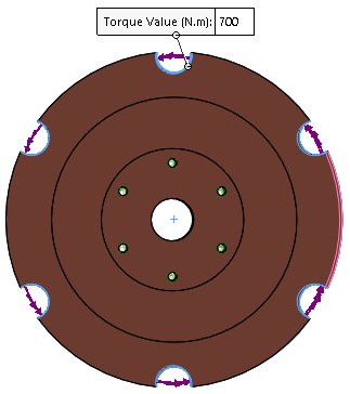
You apply a torque load of 700 Nm at the outer cylindrical faces of the
disk where bolts attach the inner disk to the outer disk rotor.
The
faces to which you apply a torque load and the cylindrical face for the torque direction
are preselected in the FeatureManager design tree under and .
-
In the
Optimization study tree, right-click
External Loads
 , and click Torque
  .
.
-
In the graphics area, expand the brake rotor flyout Feature Manager design tree. Under
Selection Sets, select load.
The six cylindrical faces of the outer bolt circular
pattern appear in
Faces for Torque

.
-
Click Axis, Cylindrical Face for
Direction
 . In the brake rotor flyout Feature Manager design tree,
under Selection Sets, select load direction.
. In the brake rotor flyout Feature Manager design tree,
under Selection Sets, select load direction.
The exterior cylindrical face is selected for the torque
load direction.
-
For Torque value
, type 700.
A 700 Nm torque is applied to each of the 6 selected
cylindrical faces. A total torque of 4200 Nm is applied to the inner disk
rotor.
-
Click
 .
.