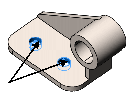
For static analysis, you must apply adequate fixed restraints to stabilize the model. In this example, you fix the two holes at the base of the part.
-
Click the down arrow on Fixtures
Advisor
 (Simulation CommandManager) and select Fixed
Geometry, or right-click Fixtures
 in the study tree and select
Fixed Geometry
 .
.
The Fixture
PropertyManager appears.
- In the graphics area, click the faces of the two holes shown in the figure.
Face<1> and Face<2> appear in the
Faces, Edges, Vertices for
Fixture

box.

To change the color of the restraint symbols, click
Edit Color under Symbol Settings. A color palette opens.
Select the required color and click OK.
-
Click
 .
.
The software fixes the faces of the two holes and
creates an icon named
Fixed-1

in the
Fixtures folder of the Simulation study tree.