Define the motor displacement profile from Function Builder displacement
segments that are piecewise continuous with respect to time. By selecting the default
interpolation method, the resulting motor displacement profile is created from a sequence of
cubic splines over the time segments that you specify.
When you specify the motor profile from displacement values over time segments,
the resulting motion displacement has a piecewise continuous profile in time. You
specify the displacement value at each segment end time. The calculated motion
values are interpolated between the end times to produce a continuous profile over
each segment that you specify.
Specifying a motor profile from displacement segments over time is well-suited for event-based motion studies.
-
Right-click PathMateMotor1
 in the MotionManager tree and click
Edit Feature
 .
.
- Under Motion, select Segments for Function.
The Function Builder appears.
- In the segment table, click Click to add row twice.
-
Modify the rows of the table as follows:
| Start X |
End X |
Value |
| 0.0 s |
0.6s |
15.0 in |
| 0.6 s |
1s |
35.9 in |
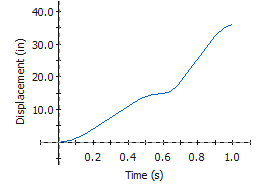
Entering these values, along with the default cubic
interpolation method specifies the displacement profile with the following characteristics:
- The motion starts at zero displacement at time 0
sec.
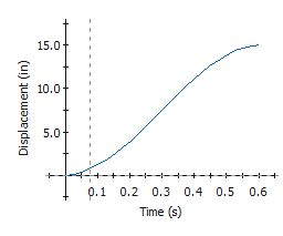
- The displacement increases according to a cubic
polynomial to 15 inches at 0.6 sec.

- The displacement increases according to a cubic
polynomial to 35.9 inches at 1 sec.

-
Click OK and click
 .
.
-
Click Calculate
 (MotionManager toolbar).
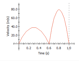
Since 35.9 is the length of the sketched path, the path mate motor
specifies the motion for one cycle. The guide has zero velocity at the segment
end times of 0.6 sec and 1 sec, as shown in the
Function Builder.

To open the
Function Builder, repeat Step 1,
and in the PropertyManager under Motion, click Edit.