Constructing Construction Lines
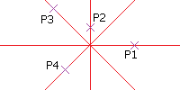
Construction lines extend indefinitely in both directions from an origin. Use Construction lines to create frameworks or grids for use in drawing construction.
Construction lines are placed on a specific Layer.
The separte layer for construction lines lets you to turn off or freeze prior to printing and delete them when the drawing is complete.
To construct one or more construction lines:
- Do one of the following:
- On the ribbon, click Home > Construction Lines > Construction Lines.
- On the menu, click Draw > Construction Line.
- Type AM_ConstLine at the command prompt.
- In the graphics area specify:
- The central position of the construction line.
- The through point to define the first construction line direction.
- Different through points to define other construction lines through the same origin, or press Enter.

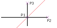
To create horizontal construction lines:
- Do one of the following:
- On the ribbon, click Home > Construction Lines > Horizontal.
- On the menu, click Draw > Construction Line, then specify Horizontal.
- Type AM_ConstLine at the command prompt, then specify Horizontal.
- In the graphics area, specify:
- A point to define the construction line position.
- Other points to define parallel horizontal construction lines, or press Enter.
To create vertical construction lines:
- Do one of the following:
- On the ribbon, click Home > Construction Lines > Vertical.
- On the menu, click Draw > Construction Line, then specify Vertical.
- Type AM_ConstLine at the command prompt, then specify Vertical.
- In the graphics area, specify:
- A point to define the construction line position.
- Other points to define parallel vertical construction, or press Enter.
To create parallel construction lines at an angle from the origin:
- Do one of the following:
- On the ribbon, click Home > Construction Lines > Angle.
- On the menu, click Draw > Construction Line, then specify Angle.
- Type AM_ConstLine at the command prompt, then specify Angle.
- Type an angle value in the specified angle drawing units or specify the Reference option to specify a reference entity, and then enter the angle from the reference entity.
The construction line appears at the specified angle to the horizontal or to the specified entity.
- In the graphics area, specify:
- A point to define the line position.
- Other points to define parallel lines, or press Enter.
To create bisecting construction lines from a vertex:
- Do one of the following:
- On the ribbon, click Home > Construction Lines > Angle Bisect.
- On the menu, click Draw > Construction Line, then specify Angle Bisect.
- Type AM_ConstLine at the command prompt, then specify Angle Bisect.
- In the graphics area, click:
- A point to define the vertex position.
- A point to define the first angle for the bisecting construction line.
- A point to define the second angle that determines the bisecting construction line through the vertex.
- Other points to define other bisecting construction lines, or press Enter.

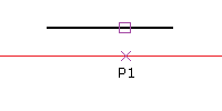
To create construction lines that are offset from other linear entities:
- Do one of the following:
- On the ribbon, click Home > Construction Lines > Offset.
- On the menu, click Draw > Construction Line, then specify Offset.
- Type AM_ConstLine at the command prompt, then specify Offset.
- Type an offset distance.
- In the graphics area:
- Select a linear source entity.
- Click where you want to place the construction line.
- Repeat step 4 or press Enter.
 Note: Instead of performing steps 3 and 4, you can specify the Specify Position option, select a linear source entity, and specify a point in the graphics area to define the offset distance.

Command: AM_ConstLine
Menu: Draw > Construction Line
Ribbon: Home > Construction Line > Construction Line