Creating Flat Representations of 3D Solid Objects
The MakeFlatSnapshot command creates a flat representation of 3D solid objects and Regions, projected to the drawing's X-Y plane of the active Custom Coordinate System (CCS).
The 2D flattened representation can be inserted as a Block in the XY plane of the active CCS.
You can show or hide hidden lines and tangent edges in the flat representation. Additionally, you can change the color and style of the foreground and hidden lines.
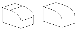
Tangent edges are visible transition edges between curved surfaces or curved and flat surfaces.
Example: Filleted edge with and without tangent edges.
To create a flat representation of 3D solid objects:
- In the graphics area, set up a view from which you want to make a flat snapshot. Use the Views command.
- Click Solids > Solid Editing > Make Flat Snapshot (or type MakeFlatSnapshot).
- In the dialog box, specify an option for Flat Snapshot Destination:
- Insert as Block: Inserts the flat representation as a Block in the graphics area.
- Replace existing Block: Replaces an existing Block in the drawing with the Block you created.
- Export to file: Saves the flat representation to an external drawing file.
- Optionally, select Show tangent edges to display tangent edges in the flat representation.
- Change the line color and style in the flat representation:
- Under Foreground lines, specify the color, the line style, and the line layer for the foreground lines.
- Under Hidden lines, select Show to display the hidden lines. You can modify the color, the line style, and specify the line layer for the hidden lines.
- Click OK.
 Use the Explode command to break the Block representing the flattened view into its component entities. Exploding the Block lets you remove obscured lines or modify the LineStyle of hidden lines.
Command: MakeFlatSnapshot
Menu: Solids > Solid Editing > Make Flat Snapshot
Ribbon: Insert > Block > Make Flat Snapshot