Defining Levels
Use the BIMLevels command to define levels in vertical views, such as elevations and sections.
In BIM drawings, levels are auxiliary elements that indicate the altitude of floors, foundations, and the roof of buildings.
Example:
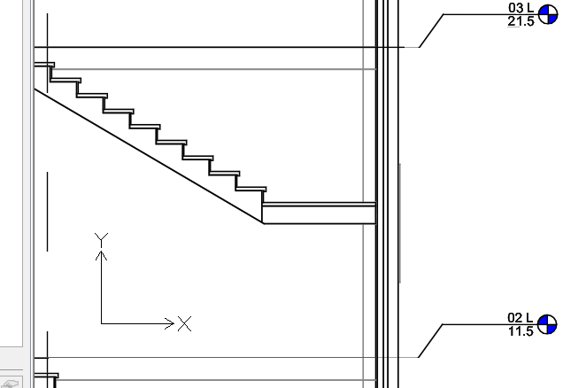
Levels consist of the following elements:
- Central segment
- Start segment
- End segment
- Symbols (bubbles)
To define a level:
Note: You can add levels only in elevations and vertical sections.
- Do one of the following:
- On the ribbon, click BIM > Annotate > Levels.
- On the menu, click BIM > Levels.
- Type BIMLevels.
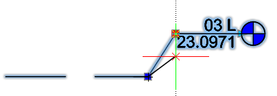
- In the graphics area, specify the first level point.
- Move the cursor horizontally and specify the second level point.
- In the command window, type the name of the level and press Enter.
- Repeat steps 2 to 4 as needed to define other levels.
Customizing Levels
Using the Properties palette you can change the appearance of the levels.
You can do the following:
- Hide segments of the level line. For example, the central segment.
- Show or hide level symbols
- Change the line color, weight, and type. For example, you can use a different color to represent the central segment.
Additionally, you can adjust the position of the level symbols using grip points. In case of overlapping level symbols, grip points let you offset the bubbles.
To show or hide level symbols:
By default, level symbols appear at both ends of a level line.
- In the graphics area, specify a level.
- In the Properties palette, in Visibility, specify Yes or No to show or hide the desired level symbol:
To move levels:
- In an elevation or vertical section, select the level to move.
- Click and drag the level to the new position.
To offset a level line from its symbol:
- In an elevation or vertical section, specify the level to modify.
The level is selected and the grip points are displayed.
- Click and drag the grip point near the level symbol to move the symbol to the desired location.
Command: BIMLevels
Menu: BIM > Levels
Ribbon: BIM > Annotate > Levels