The general spring connector is available with SOLIDWORKS Simulation
Professional and SOLIDWORKS Simulation Premium.
You can use general spring connectors between these types of geometric
entities:
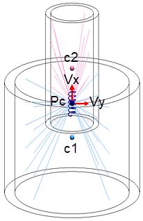
- Concentric cylindrical faces
Two reference nodes
of a spring connector are colocated at the point of interaction (Pc), which
is located midpoint between the centroids (c1 and c2) of the two cylinders.
You define the spring's resistance to relative translation and rotation of
the reference nodes with six stiffness parameters. One reference node of the
spring connects to the coupling nodes of cylindrical surface 1 with
distributed coupling, and the second reference node connects similarly to
the coupling nodes of cylindrical face 2.
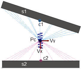
- Nonparallel and parallel flat surfaces
Two
reference nodes of a spring connector are colocated at the point of
interaction (Pc), which is located midpoint between the centroids (c1 and
c2) of the two flat surfaces. A general spring formulation enforces
distributed coupling between the spring's reference nodes and the coupling
nodes located at the flat surfaces.
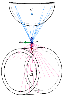
- Nonflat
surfaces
Two reference nodes of a spring connector are
colocated at the point of interaction (Pc), which is located midpoint
between the centroids (c1 and c2) of the spherical and cylindrical surfaces.
A general spring formulation enforces distributed coupling between the
spring's reference nodes and the coupling nodes located at the
surfaces.
For each general spring connector, you can define up to six stiffness
parameters, a local coordinate system, and a preload force per unit length.