 |
Bodies for Flex |
Select bodies to flex. |
| |
Flex types |
Determines the type of flex. To create more than one type of flex, create separate flex features. Choose from these types: |
| |
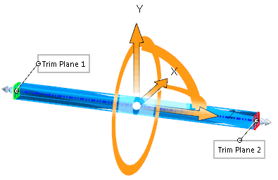
Bending |
Bends one or more bodies about the triad’s red X-axis (the
bend axis). Position the triad and trim planes to control the
degree, location, and extent of bending. This flex type can be used
for many applications including industrial design, mechanical
design, solving spring-back conditions in metal stamping, removing
undercuts from complex surface shapes, and so on. The neutral plane of the bend passes through the
triad origin and corresponds to the triad’s X-Z plane. The arc
length between the trim planes along the neutral plane stays
constant throughout the bending operation.
Set these
options:
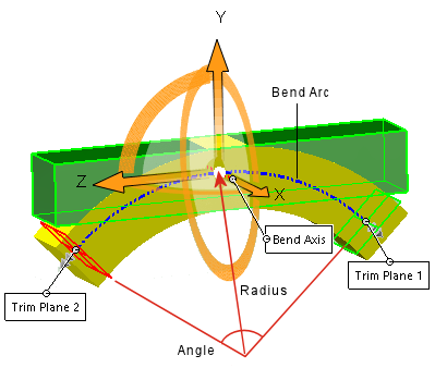 The length
of the bend arc between the trim planes does not change and
is equal to the Angle x the
Radius. Therefore, you can
specify the Angle or
the Radius. The
option you specify drives the other value.
|
Angle 
|
Sets a bend angle and works with the
bend Radius
 . .
|
|
Radius
|
Sets the bend radius.
|
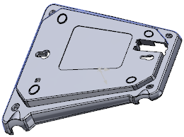
| Example of
Bending |
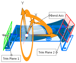 |
- Move the pointer over the
triad arrows to display the drag/rotate pointer
 .
Right-click to rotate the triad, which changes the
direction of bend. Left-click to reposition the
triad. .
Right-click to rotate the triad, which changes the
direction of bend. Left-click to reposition the
triad.
- Move the pointer over the trim
plane manipulators to display the move pointer
 . Drag the manipulators to position the trim
planes. . Drag the manipulators to position the trim
planes.
- Move the pointer over the edge
of the trim planes to display the bending pointer
 . .
- Drag the trim planes to bend
and modify the flex feature.
|
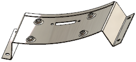 |
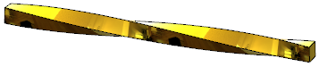
| Result of
Bending |
|
| |
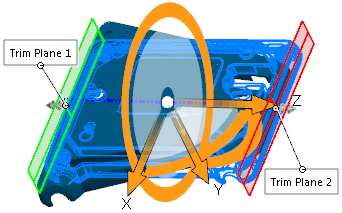
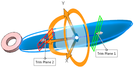
Twisting |
Twists solid and surface bodies around the blue Z-axis of the triad. Position the triad and trim planes to control the degree, location, and extent of twisting.
Set this option:
|
Angle
|
Sets the angle of twist.
|
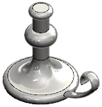
| Example of Twisting |
|---|
 |
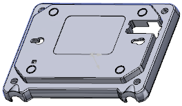
| Initial part with ribs |
 |
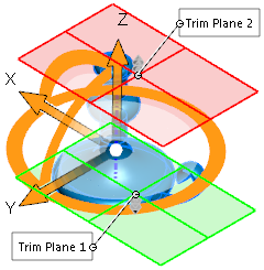
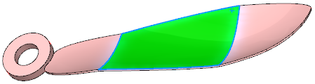
| Twist preview. The flex region is constrained by the trim planes. |
 |
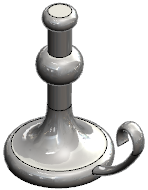
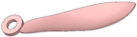
| Result of Twisting |
|
| |
Tapering |
Tapers solid and surface bodies along the blue Z-axis of the triad. Position the triad and trim planes to control the degree, location, and extent of tapering.
Set this option:
|
Taper factor 
|
Sets the amount of taper. The trim planes do not move when you adjust the Taper factor .
|
| Example of Tapering |
|---|
 |
| Initial part |
 |
| Taper preview.
The flex region is constrained by the trim planes. |
 |
| Result of Tapering |
|
| |
Stretching |
Stretches solid and surface bodies along the blue Z-axis of the triad.
Specify a distance or drag the edge of a trim plane with the left mouse button. Set this option:
|
Stretch distance
|
Sets the amount of stretch.
|
| Example of Stretching |
|---|
 |
| Initial part |
 |
| Stretch preview.
The flex region is constrained by the trim planes. |
 |
| Result of Stretching |
|
| |
Hard edges |
Creates analytical surfaces (cones, cylinders, planes, and so on), which often result in split faces where the trim planes intersect the bodies. If cleared, results are spline-based, so surfaces and faces may appear smoother and original faces remain intact.
| Example of Hard Edges |
|---|
 |
| Twist with the trim planes repositioned to limit the region of twist. |
 |
Result with Hard edges selected.
The face is divided into separate faces where the trim planes intersect the part.
|
 |
Result with Hard edges cleared.
The face remains one face.
|
|