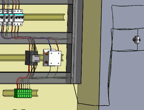
Routing wires generate a 3D representation of the wire path within the
electrical installation. The routing paths and connection points facilitate the routing
process.
Segregation manages the rules applied to the wire paths.
Route Wires routes only the
wires in an electrical project.
To access Route Wires:
- SOLIDWORKS Electrical 3D menu: Route Wires
 .
.
- Menu:
 .
.
When you run Route Wires, the
left dockable panel changes to display various options. Several of these parameters
are saved in the SOLIDWORKS Electrical file and are specific to the file. The others
are saved in the registry and are common to all SOLIDWORKS Electrical files.
Routing Analysis
Show errors. Displays a report
at the end of the routing that shows all routing errors. Click Help on a line of the report for information about
the error.
Select route type
- SOLIDWORKS Route.
Routes the wires as managed by SOLIDWORKS, accounting for wire
diameters.
- 3DSketch Route.
Routes the wires as a 3D sketch. This mode is quicker and better for
temporary routings.
Select geometry type
- Use splines. Uses
splines (curves) to ensure optimal rendering of the wire routing. When you
use splines in the routing path, you can manually add points on it to
improve the routing.
- Use lines. Generates
a wire routing with straight lines. Add
Tangency inserts curves at the end of the straight
lines.
Components to route
- All components.
Launches routing across all components in the assembly.
- Route active location
only. Limits the routing of wires to the top-level
assembly only.
This supports creating
SOLIDWORKS Route and
3DSketchRoute route
types.
- If the wires at the top-level active
location have their origin or destination components in
another location or sublocations of the electrical
project, only those wires get routed along with the
wires belonging to the components of the active
top-level location.
- If the wires at the top-level active
location have their origin or destination components in
another location that is out of scope (for example, the
active location is a sublocation, and a wire is at the
top location), the wire is not routed.
- Selected components.
Launches routing across a subsection of the components. Select the
components in the graphics area. Only the wires connected to the selected
components are routed.
Routing parameters
The first parameter specifies the distance between two routing
paths.
The second parameter specifies the distance between a connection
point and routing path.
The third parameter specifies the distance between two wires.
The graph lets you quickly view connections between components. There
are two buttons available: one for display, and the other for deleting the
graph.

Shortest Path Algorithm
For
Algorithm, choose from the following:
- Dijkstra. A classic routing
algorithm that works best if there are only a few routes (less than 100). It
is a fallback option if Floyd Warshall fails.
- Floyd Warshall. A
highly parallelized algorithm that uses a graphics card for calculations. It
works best if there are
many
routes (more than 100).