DimXpert for parts supports many manufacturing features.
|
Feature |
Example |
Topology |
Corresponding SolidWorks Feature |
|
Boss |
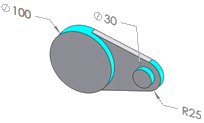
The dimensioned diameters represent boss features. |
An external cylindrical face having a complete 360 degrees of arc |
No |
|
|
|
|
|
|
Chamfer |
|
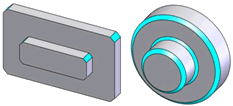
A planar or conical face or swept line. See DimXpert Chamfer Control Options
for maximum width and chamfer width ratios |
Yes.
Chamfer
features defined using Angle distance
and Distance distance |
|
|
|
|
|
|
|
|
|
|
|
Cone |
|
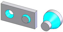
An internal or external conical face |
No |
|
|
|
|
|
|
Cylinder |
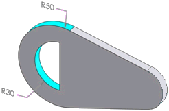
The 30, and 50 degree radii represent cylinder features. |
A partial or full internal or external cylindrical face
External faces with complete 360 degrees of arc may be classified as
boss features |
No |
|
|
|
|
|
|
Feature |
Example |
Topology |
Corresponding SolidWorks Feature |
|
Fillet |
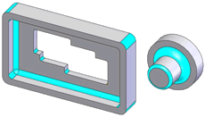
|
A cylindrical face or swept arc:
Up to 180 degrees of arc Cylindrical faces are tangent to supporting faces,
when present Chained (concatenated) faces have tangency and
equal radii |
Yes.
Constant radius fillet
features |
|
|
|
|
|
|
Counterbore Hole |
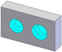
A typical
counterbore hole (left), and a stepped hole with a blind bottom defined
as a counterbore hole (right) |
A hole series including two concentric cylinders separated by a plane
perpendicular to their axes, with or without a blind end condition of
type plane or conic |
Yes.
Hole
Wizard counterbore.
If you define a counterbore hole using the Head
clearance or Near side countersink
options, DimXpert cannot recognize it as a counterbore hole. |
|
|
|
|
|
|
Countersink Hole |
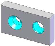
A typical
countersink hole (left), and a chamfered hole defined as a countersink
hole (right) |
A hole series including a cone followed by a concentric cylinder, with
or without a blind end condition of type plane or conic |
Yes.
Hole
Wizard countersink.
If you define a countersink hole using the Head
clearance or Far side countersink
options, DimXpert cannot recognize it as a countersink hole. |
|
|
|
|
|
|
Feature |
Example |
Topology |
Corresponding SolidWorks
Feature |
|
Simple Hole |
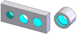
(Left) From left to right, a threaded hole with a drill tip bottom,
a through hole, and a hole with a flat bottom.
(Right) A compound hole comprised of two cylindrical surfaces. |
A hole series including a cylindrical face having more than 180 degrees
of arc, with or without a blind end condition of type plane or conic |
Yes.
Hole
Wizard and Simple
Hole features
Holes with near side countersinks are recognized as countersink holes
(not linked holes) |
|
|
|
|
|
|
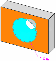
Intersect Circle |
|
A circle derived at the intersection of
a cone and plane. The cone must be perpendicular to the plane, and it
cannot be created from an ellipse. The cone and plane can be interrupted
by a fillet or chamfer. |
N/A |
|
|
|
|
|
|
Intersect Line
|
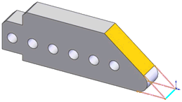
An intersect line (blue) forms at the intersection of the part’s bottom
plane and the skewed plane (orange).
Intersect lines are typically used for dimensioning. In this example,
you may need to locate the intersection of the two planes to the left-hand
side of the part to control its length. |
A line derived at the intersection of two planes |
N/A |
|
|
|
|
|
|
Intersect Plane |
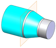
An intersect plane is derived at the intersection of the larger cylinder
and conical face.
Intersect planes are typically used to locate the starting or ending
location of a tapered surface. |
A plane derived at the intersection of a concentric cylindrical and
conical face. |
N/A |
|
|
|
|
|
|
Feature |
Example |
Topology |
Corresponding SolidWorks Feature |
|
Intersect Point |
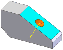
An intersect point, shown as an origin, is derived at the intersection
of a plane (blue) and a cylinder (orange).
Intersect points are typically used to locate the referencing hole/cylinder.
In this example, you may need to locate the hole's pierce point to the
right-hand side of the part (creating a horizontal dimension). |
A point derived at the intersection of a plane and the axis of a cylindrical
or conical face. |
N/A |
|
|
|
|
|
|
Notch |
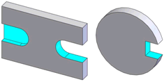
|
Two parallel planes bounded by a plane perpendicular or a cylinder tangent
to the side planes, with or without a planar blind end condition |
No |
|
|
|
|
|
|
Plane |
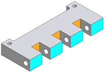
Each planar face (gray) represents a single plane feature. You can combine
the blue or orange faces to define a compound plane. |
A planar face |
N/A |
|
|
|
|
|
|
Feature |
Example |
Topology |
Corresponding SolidWorks Feature |
|
Pocket |
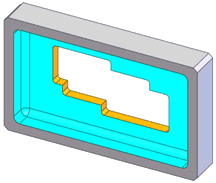
An example of a through pocket (orange) embedded in a blind pocket (blue) |
An internal extruded type closed profile, with or without a planar blind
end condition |
No |
|
|
|
|
|
|
Slot |
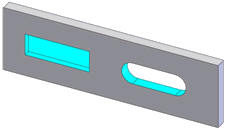
A blind square slot (left) and a through slot with radial ends (right) |
Two parallel planes bounded by two planes perpendicular or two cylinders
tangent to the side planes, with or without a planar blind end condition |
No |
|
|
|
|
|
|
Surface |

|
A non-prismatic face |
No |
|
|
|
|
|
|
Feature |
Example |
Topology |
Corresponding SolidWorks Feature |
|
Width |
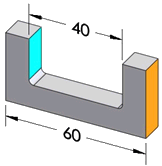
The pairs of planes that comprise each dimension represent a width feature |
Two parallel planes with opposing normal vectors |
No |
|
Sphere |
|
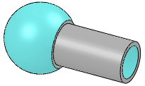
An internal or external spherical face |
No |