DimXpert for Parts - Overview
DimXpert for parts is a set of tools you use to apply dimensions and
tolerances to parts according to the requirements of ASME Y14.41-2003
and ISO 16792:2006. You can then use the tolerances with TolAnalyst to perform stack
analysis on assemblies, or with downstream CAM, other tolerance analyses,
or metrology applications. See also Xperts
Overview.
 Set Overall
drafting standard to ANSI
(ASME) or ISO under Tools,
Options, Document
Properties, Drafting Standard.
Set Overall
drafting standard to ANSI
(ASME) or ISO under Tools,
Options, Document
Properties, Drafting Standard.
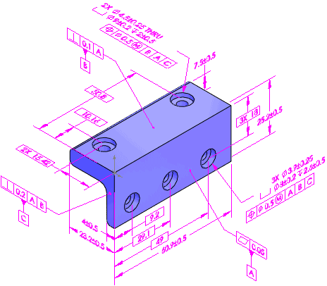
Features
For DimXpert, features means manufacturing
features. For example, in the CAD world, you create a "shell"
feature, which is a type of "pocket" feature in the manufacturing
world.
Supported manufacturing features:
|
|
Counterbore hole Countersink hole Simple hole Intersect circle Intersect line Intersect plane Intersect point |
Notch Plane Pocket Slot Surface Width Sphere |
Feature Recognition
When you apply DimXpert dimensions to manufacturing features, DimXpert
uses these methods in this order to recognize features:
Model feature recognition
Topology recognition
Model Feature Recognition
The benefit of model feature recognition is that identified features
update if you modify the model feature, especially if you add features
or faces. DimXpert recognizes these design features:
Chamfer
Cosmetic thread
Certain extrudes (for pattern extraction)
Fillet
Hole Wizard hole
Simple hole
Certain patterns (bosses, cones, width, linear,
circular, and mirror for pattern extraction)
Topology Recognition
If model recognition fails to recognize features, DimXpert uses topology
recognition. The benefit of topology recognition is that it recognizes
manufacturing features that model recognition cannot, such as slots, notches,
and pockets. Only topology recognition is used for features on imported
bodies. Topology features update if you make geometry changes, but new
instances are not added to pattern features.
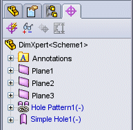
Using DimXpert
|
Use a suite of DimXpert tools to insert dimensions and tolerances manually
or automatically. The DimXpertManager:
To change the tree display,
right-click the part name in the DimXpertManager, select Tree
Display, and select a display option. |
|
To use DimXpert for parts:
Open a part to dimension using DimXpert.
Set the DimXpert options. Click Tools,
Options, Document
Properties, and set the various DimXpert
options, such as Geometric
Tolerance.
Insert dimensions and geometric tolerances manually
or automatically.
To manually insert
dimensions and geometric tolerances:
Set the datums using the Datum
 tool.
tool.
Add tolerances and dimensions using the
DimXpert
tools, such as Size
Dimension  , Location Dimension
  , Pattern
Feature
, Pattern
Feature  , and Geometric Tolerance
  .
.
Use the feature selector to define
the feature types.
Click Show Tolerance Status
 to
see which features are under or over constrained for size and location.
to
see which features are under or over constrained for size and location.
Apply additional dimensions and tolerances
as needed to fully constrain the part.
To set the color of DimXpert
dimensions, click Options  , System Options,
Colors. Under Color
scheme settings, select Annotations,
DimXpert.
, System Options,
Colors. Under Color
scheme settings, select Annotations,
DimXpert.
To automatically insert dimensions and geometric
tolerances:
Click Auto Dimension Scheme  (DimXpert toolbar) or Tools,
DimXpert, Auto
Dimension Scheme.
(DimXpert toolbar) or Tools,
DimXpert, Auto
Dimension Scheme.
Set the PropertyManager options.
Click  .
.
Save the part.