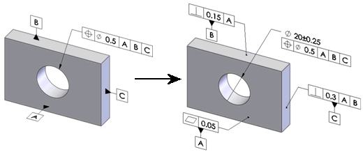
DimXpert Geometric Tolerance
Use the DimXpert Geometric Tolerance
tool  to apply geometric tolerances to DimXpert features.
To use DimXpert to apply a geometric tolerance:
Click Geometric
Tolerance  (DimXpert toolbar) or Tools,
DimXpert, Geometric
Tolerance.
Select the geometric characteristic.
Apply the tolerance information and datums as
required.
Select a feature and place the annotation.
You can also pre-select a feature.
Click OK.
 You can also set geometric tolerance attachment options.

Properties Dialog Box
Use the geometric tolerance Properties
dialog box to define and edit DimXpert geometric tolerances. When you
use the Properties dialog box
from DimXpert, the software offers these filters and checks, per the active
drawing standard.
|
Property |
Filters and Check |
|
Symbol |
Check: The software checks to
ensure the geometric characteristic and feature combination is valid.
An error occurs if the combination is invalid, for example, if you apply
Flatness when the toleranced feature
is a Boss. |
|
|
|
|
Tolerance Zone Shape |
Filters: The software filters
the options based on the selected geometric characteristic. For example,
the options are enabled for Position
tolerances and disabled for Circularity
tolerances.
Check: The software checks to
ensure the tolerance zone and feature combination is valid. An error occurs
if the combination is invalid, for example, if you apply a diameter symbol
when the toleranced feature is a plane. |
|
|
|
|
Tolerance Value |
Check: The software checks to
ensure the tolerance value is given and is a positive number. An error
occurs if the value is missing, is not a number, or is less than zero. |
|
|
|
|
Material Condition Modifier |
Filters: The software filters
the options based on the selected geometric characteristic. For example,
the options are enabled for Position
and disabled for Runout.
Checks:
The software checks to ensure the maximum material
condition (MMC) and least material condition (LMC) symbols are applied
only when the toleranced feature is a feature of size. An error occurs
when the feature is not a feature of size, for example, when the feature
is a pocket. The software checks to ensure a size tolerance
is applied to the toleranced feature when you specify MMC or LMC. An error
occurs when a size tolerance does not exist. |
|
|
|
|
Projected Tolerance Zone |
Filters: The software filters
the options based on the selected geometric characteristic. For example,
the options are enabled for Position
and disabled for Concentricity.
Checks:
The software checks to ensure the toleranced feature
supports a projected tolerance zone. An error occurs if the feature does
not. For example, if you apply
a projected tolerance zone when the feature is a plane (ISO). The software checks to ensure the height value
is given and is a positive number. An error occurs if the value is missing,
is not a number, or is less than zero. |
|
|
|
|
Unit Basis Tolerance |
Check: The software checks to
ensure the format used for the per unit area or per unit length criteria
is valid. An error occurs when the format is not recognized. |
|
|
|
|
Tolerance 2 |
Check: The software checks to
ensure the format of the input, tolerance value followed by “MAX”, is
valid. An error occurs when the format is not recognized. |
|
|
|
|
Primary, Secondary, and Tertiary Datum |
Filters:
The software filters the datum options based on
the selected geometric characteristic. For example, the options are enabled
for Position and disabled for
Flatness. The software filters the options for the material
condition modifiers based on the selected geometric characteristic. For
example, the options are enabled for Position
and disabled for Runout.
Checks:
The software checks to ensure the entered datum
label is the label of an existing datum. An error occurs when it is not. The software checks to ensure MMC and LMC symbols
are only applied when the datum feature is a feature of size. An error
occurs when the feature is not a feature of size, for example, when the
feature is a plane. The software checks to ensure the datums define
a valid datum reference frame based on the rules specified by ASME Y14.5.1M.
An error occurs for non-conforming datum sets, for example, if the primary
and secondary datums are two parallel planes. |
|
|
|
|
Composite Frame |
Check: When you specify datums,
the software checks to ensure the datums specified in the lower tier are
entered in the same order of precedence as the upper tier. An error occurs
if the datums do not repeat, for example, if the primary datum in the
upper tier is “A,” but “B” is entered as primary in the lower
tier. |
Inch Parts
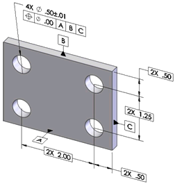
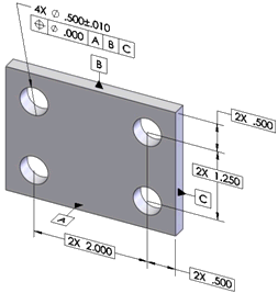
When working in inches, the number of significant
digits and trailing zeroes you enter into the tolerance compartment controls
the number of decimals used when creating the basic dimensions.
The tolerance value entered as
“.00”
The basic dimensions are expressed in the
same number of decimals as the tolerance value. |

|
|
The tolerance value entered as “.000” |

|
Direction Dependant Tolerances
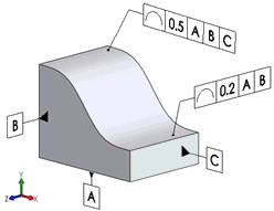
When applying tolerances that control the line elements of a feature,
or when applying planar zone tolerances to axial features, be careful
when setting the annotation planes. In the example below, the 0.5
tolerance applies to all line elements lying in planes parallel to datum
B, and the 0.2
tolerance applies to all line elements lying in planes parallel to datum
C.

List of supported tolerances by feature.
Boss, Cone, Cylinder, Simple Hole
Form: circularity, cylindricity (except cone),
straightness
Orientation: angularity, parallelism, perpendicularity
Location: concentricity, position, symmetry (ISO
only)
Profile: line, surface
Runout: circular, total
Counterbore and Countersink Holes
Plane
Form: flatness, straightness
Orientation: angularity, parallelism, perpendicularity
Location: position (ISO only), symmetry
Profile: line, surface
Runout: circular, total
Notch, Slot, Width
Form: straightness (width only)
Orientation: angularity, parallelism, perpendicularity
Location: position, symmetry
Profile: line, surface
Pocket
Location: position
Profile: line, surface
Collection, Surface
Sphere
Related Topics
DimXpert
Geometric Tolerance Options