Alternate Position View
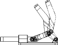
Alternate Position Views indicate
the range of motion of an assembly component by showing it in different
positions. You can overlay one or more Alternate Position Views on the
original view in a phantom font.
Example of an Alternate Position
View:
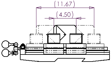
You can dimension between the primary view and
the Alternate Position View.
The Alternate Position View is added to the FeatureManager
design tree.
You can create more than one Alternate Position
View in a drawing.
The Alternate Position View is not available in
Broken, Section, Crop, or Detail views.
After you
create an Alternate Position View, you can modify it at the assembly and
drawing levels.
To insert an alternate position view:
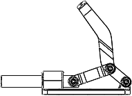
Insert a model view of the assembly using the
orientation needed for the Alternate Position View. Position the assembly
in its starting position. |
|
-
Click Alternate Position View  on the Drawing toolbar, or click Insert, Drawing View,
Alternate Position. on the Drawing toolbar, or click Insert, Drawing View,
Alternate Position.
The Alternate Position PropertyManager
appears. You are prompted to select a drawing view in which to insert
the alternate position.
Under Configuration, choose either:
New configuration
- to create a new Alternate Position configuration. Accept the default
name or type a name of your choice. This option activates the new configuration
in the assembly. Existing configuration
- to choose an existing configuration in the assembly document. Select
a configuration from the list. |
|
Click OK
 . The results are either: . The results are either:
New configuration
- If the assembly document is not already open, it opens automatically.
The assembly's view orientation changes to that of the drawing view. The
assembly appears with the Move Component
PropertyManager open and Free Drag
activated. Continue to Step 5. Existing configuration
- The alternate position of the selected configuration appears in the
drawing view, and the PropertyManager closes. The view is complete. No
further steps are required. |
|
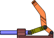
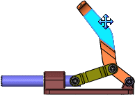
Use any of the Move
Component tools to move the assembly components to the desired
position. In the PropertyManager, under Options,
use Collision Detection and Stop at collision to stop motion. |
|
-
Click OK  to
close the Move Component PropertyManager
and return to the drawing. to
close the Move Component PropertyManager
and return to the drawing.
The alternate position of the assembly configuration appears in
the drawing view in phantom lines, and the Alternate
Position PropertyManager closes.
|
|
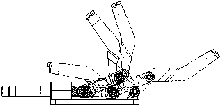
Create
as many Alternate Position Views as needed using the same steps. |
|
To edit an alternate position
view: