Hide Table of Contents

Mounting Boss

The Mounting Boss PropertyManager appears when you create a new mounting boss fastening feature.

The PropertyManager controls these properties:

Position

  • Select a face . Select a planar or non-planar face on which to place the mounting boss. The software creates a point (where you select the face) in a 3D sketch.

    To position the mounting boss, do one of the following:

    • Edit the 3D sketch, then dimension the point.

    • To place the mounting boss at an exact predefined location, before or after you create the boss, create a sketch with a point at the desired location, then select that point for Select a face .

You cannot edit the point during feature creation.

  • Select Direction (non-planar faces only). Set a direction for the boss. If not specified, the boss is placed normal to the face at the selected point. Click Reverse Direction if necessary.

  • Select circular edge (optional). Select a circular edge to position the center axis of the  mounting boss.

The projected center of the circular edge must intersect the face where the mounting boss is positioned.


Mounting boss position before selecting circular edge

Position after selecting circular edge

Boss

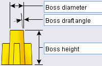
  • Enter boss height. Sets the boss parameters.

  • Select mating face. Activates the Mating face box and deactivates the Boss height box.

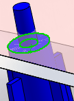
  • Mating face . Select a face to which you mate the top of the boss. The boss height is automatically calculated. If you change the height of the mating face, the boss height changes too.

    You can mate the boss to a face that does not contact the boss. For example, the mating face and the boss can be side-by-side.

    In the image, the mating face is the bottom of the lid (transparent). The boss height is automatically calculated based on the mating face. The green highlighted edges show the mating face meeting the boss. The mounting pin penetrates the lid.

Fins

  • Select a direction vector.  Select a direction vector to position one fin. Other fins position themselves automatically around the boss. Click Reverse Direction if necessary.


No draft

Draft

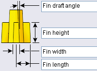
 Fin width sets the thickness at the base of the fin, before applying draft.

Fin length is measured from the center of the boss.

  • Number of fins .


  • Equally spaced. (Available for two fins only.) Creates a 180 degree angle between the two fins. This option is useful for corner bosses. Clear this option to select a direction vector that defines the second fin's orientation.

Equally spaced selected.

Equally spaced cleared.

Select a face or edge to define the orientation of the second fin.

Mounting Hole/Pin

  • Pin. Creates a mounting pin.

  • Hole. Creates a mounting hole.

Pin

Hole

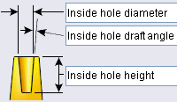
  • Enter diameter. Activates the Hole/pin diameter box.

or

  • Select mating edge. Activates the Mating edge box and deactivates the Hole/pin diameter box.

  • Mating edge . Select a mating edge to automatically define the diameter.

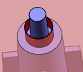
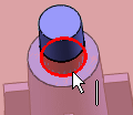
    In the images, the edge of the selected hole automatically determines the pin diameter


Pin diameter before selecting a mating edge


Pin diameter after selecting the mating edge shown

Favorite

Manage a list of favorites that you can reuse in models.

  • Apply Defaults/No Favorite . Resets to No Favorite Selected and the default settings.

  • Add or Update a Favorite . To update a favorite, edit the properties, click , and enter a new or existing name.

  • Delete Favorite

  • Save Favorite

  • Load Favorite . Click this option, browse to a folder, and select a favorite.


Provide feedback on this topic

SOLIDWORKS welcomes your feedback concerning the presentation, accuracy, and thoroughness of the documentation. Use the form below to send your comments and suggestions about this topic directly to our documentation team. The documentation team cannot answer technical support questions. Click here for information about technical support.

* Required

 
*Email:  
Subject:   Feedback on Help Topics
Page:   Mounting Boss
*Comment:  
*   I acknowledge I have read and I hereby accept the privacy policy under which my Personal Data will be used by Dassault Systèmes

Print Topic

Select the scope of content to print:

x

We have detected you are using a browser version older than Internet Explorer 7. For optimized display, we suggest upgrading your browser to Internet Explorer 7 or newer.

 Never show this message again
x

Web Help Content Version: SOLIDWORKS 2012 SP05

To disable Web help from within SOLIDWORKS and use local help instead, click Help > Use SOLIDWORKS Web Help.

To report problems encountered with the Web help interface and search, contact your local support representative. To provide feedback on individual help topics, use the “Feedback on this topic” link on the individual topic page.