Hole Tables
You can use hole tables to automatically generate hole information in a tabular format. You can create columns for model information, such as hole size and location.
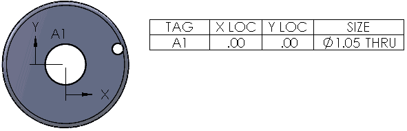
Hole tables in drawing documents measure the positions of selected holes from a specified origin datum. The software labels each hole with a tag that corresponds to a row in the table.
 Non-circular holes such as rectangles and slots are recognized as holes. The table lists the X and Y coordinates of the entities by their geometric centers, but you must enter the size.
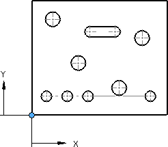
Holes that intersect other faces are not included in hole tables because the geometry is interrupted by another feature, making an incomplete hole. For example:
In addition to the functionality for all tables, in Document Properties - Hole Tables and in the Hole Table PropertyManager you can specify:
-
Tags to be alphabetic or numeric
-
Cells with the same tags to be combined
-
Cells for holes of the same size to be combined
ANSI inch letter and number drill sizes be displayed
-
Precision of hole locations
-
Dual dimension display

To set options for hole tables in the active document:
-
Click Tools > Options > Document Properties > Tables > Hole.
-
Set the options and click OK.
To create a hole table:
-
Click Hole Table  (Table toolbar) or click Insert, Tables, Hole Table.
-
In the PropertyManager, set options.
-
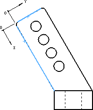
In the graphics area, select a vertex to specify the Origin.
You can select an X axis and Y axis to define a vertex for the datum. You can also drag the origin datum into position after you place the table.
|
|
|
|
Vertex selected as origin
|
Edges selected as X and Y axes
|
-
Select hole edges, or select a model face to include all cut loops within the face boundary.
If the drawing view is displayed in Wireframe  or Hidden Lines Visible
  , you can select non-through holes from the opposite face to include in the hole table. These holes are labeled FAR SIDE.
-
To include additional drawing views in the table, click Next View in the PropertyManager and repeat steps 3 and 4.
-
Click  .
.
-
If you did not select Attach to anchor point, click in the graphics area to place the table.
The table is placed on the drawing with notes added near the holes.
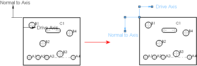
To edit the origin datum:
-
Select an axis in the graphics area, then click Edit datum definition in the Hole table axis PropertyManager.
- or -
Right-click the hole table in the FeatureManager design tree and select Edit Feature.
-
In the graphics area, select a vertex or X and Y axes.
-
Click .
The X LOC and Y LOC columns update accordingly.
-
Resize and reposition the coordinate markers by dragging them.
To change the tolerances or locating precision of holes:
You can also change the location precision of the entire table.
In an existing hole table, select a cell in the X LOC, Y LOC, or SIZE column, and change the values.
The content of the PropertyManager varies based on the column header. The SIZE column contains information from the model.
To display dual dimensions in a table:
-
Right-click the hole table and click Show dual dimensions.
-
When dual dimensions are displayed, you can display the units for the dimensions. Right-click the hole table and click Show units for dual dimensions.
To add holes to a table:
-
Right-click the hole table in the FeatureManager design tree and select Edit Feature.
-
Click in Edges/Faces, then select the holes in the graphics area.
You may have to click Rebuild  (Standard toolbar) or Edit, Rebuild to update the table.
To edit header text:
-
Double-click text in a header cell.
-
Edit the text in the cell.
To format hole tags:
-
Select a tag.
-
Set options in the Note PropertyManager.
-
Click OK .
To renumber all hole tags:
In the graphics area or the FeatureManager design tree, right-click the hole table and click Renumber All Tags.
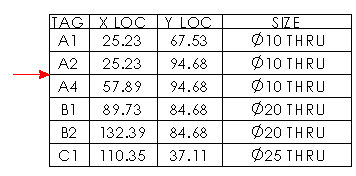
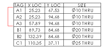
To renumber a series of hole tags:
In the hole table, right-click any row in the series and click Renumber Series.
|
|
|
|
Before renumbering series
|
After renumbering series
|
To highlight a hole on the model that corresponds to a cell in the hole table:
Right-click a cell and click Jump to Tag.
To sort a column in a hole table:
Right-click in a column and select Sort, Ascending or Descending.