Deform - Curve to Curve Examples
You can use Curve to curve deformations to:
 deformation on a complex model
deformation on an imported model
deformation to fill surfaces
Some options are only available with specific selections. See Curve to Curve Options for details about all the options.
To deform a model using curve to curve:
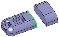
 This procedure uses a multibody part. You select the curves on one body as the Initial curves
  , and the curves along the second body as the Target curves
  .
.
-
Click Deform  on the Features toolbar, or click Insert, Features, Deform.
-
In the PropertyManager, under Deform Type, select Curve to curve.
-
Under Deform Curves, select the edges on one body in the graphics area for Initial curves .
-
Click in Target curves , then select the edges of the other body.
-
Drag to re-align the connectors to create the desired preview. Then do the following:
-
Click either of the connector handles.
-
Click the direction vector arrow on the connector handle. The pointer changes to  .
.
-
Click the direction vectors to align them in the same direction.
-
Right-click anywhere in the graphics area and select Show Connection Lines.
The connectors should be evenly distributed along the entire perimeter. If they are not, align the connectors.
Uneven distribution of the connection lines can cause twisted geometry.
-
To match the deform with tangency to both bodies, under Shape Options, select Surface tangent. Click the blue tangency direction arrows until they both point in the same direction.
The preview shows a smooth, tangent match when the tangency direction arrows are properly aligned.
-
Click OK  .
.
The deform matches the target edges with smooth, tangent connections to all target faces.
You may need to add and manipulate connector lines when using the Curve to curve deform. Additional connectors allow you to improve the quality of results. You can better match bodies that have an unequal number of edges or sharp edges (discontinuities).
The next example demonstrates changing, adding, and aligning connectors to improve the deform.
To improve a deform using connectors:
-
Click Deform on the Features toolbar, or click Insert, Features, Deform.
-
In the PropertyManager, under Deform Type, select Curve to curve.
-
Under Deform Curves, select the edges on one body in the graphics area for Initial curves . Then click in Target curves and select the edges of the surface in the graphics area.
-
Right-click anywhere in the graphics area and select Show Connection Lines.
The connection lines show the general parameters (connection) between the initial and target edges. The alignment of the connection lines in this case can be changed to improve the results.
-
To change the alignment of the connection lines, right-click and select Add Connector.
A new connection line with blue handles appears.
-
On the initial and target edges, drag the connection line handles to new positions. This results in a new alignment of the connection lines between the bodies and can improve the deform.
-
Add connectors as needed to improve the deform between the bodies. In general, the best results are achieved when the connector lines are perpendicular to the initial and target curves or edges.
-
Click OK .
If you encounter problems such as the error message Could not replace geometries, under Shape Options, move the Shape accuracy slider. Other solutions include adding additional connectors and re-aligning existing connectors.
The resulting model was created with the revised connection lines and with Surface tangent selected.