The Section View PropertyManager opens when you create a section view in a drawing and click Edit sketch in the PropertyManager, or when you select an existing section view.
Section Line
 |
Flip direction |
You can also reverse the cut direction by double-clicking the section line.
|
 |
Label |
Edit the letter associated with the section line and section view.
|
| |
Font |
To choose a font for the section line label other than the document's font, clear Document font and click Font. If you change the section line label font, you can apply the new font to the section view label.
|
Section View
| Partial section |
Creates a section view that is limited by the length of the section line if the line does not span the entire view.
|
| Display only cut faces |
Shows only the faces cut by the section line.
|
| |
Complete section
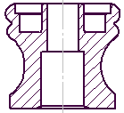
|
Partial section

|
Display only cut faces
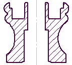
|
| Auto hatching |
Crosshatch patterns alternate between components in assemblies, or between bodies in multibody parts and weldments. The hatch patterns alternate when sectioning an assembly.
|
 |
| Display surface bodies |
Shows all surface bodies in the section view of the model.
|
| Hide cutting line shoulders |
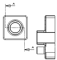 |
| Foreshorten view |
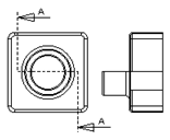 |
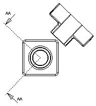
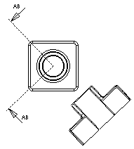
| Toggle Alignment |
Click to change the alignment of the section view.
 |
Section Depth
Lets you set the depth of a section view to a distance you specify. This control is only available for section views whose cutting line consists of a single line segment.
Distance section views apply to components, not features.
To set a distance, do one of the following:
- Set a value for Depth
 .
.
- Select geometry, such as an edge or an axis, in the parent view for Depth Reference
 .
.
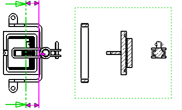
- Drag the pink section plane in the graphics area to set the depth of the cut. All components between the section line and section plane will be shown in the section view.
| Preview |
 |
Import annotation from
| Import annotations |
Select Import annotations to all selected types of annotations to be imported from referenced part or assembly documents.
Select annotation import options:
- Design annotations
- DimXpert annotations
- Include items from hidden features
|
Display State
For assemblies only. Select a display state of the assembly to place in the drawing.
The hide/show

display state is supported by all display styles. Other display states (
display mode 
,
color 
, etc.) are supported by
Shaded with Edges 
and
Shaded modes 
only.
Display Style
| Use parent style |
Clear to select style and quality settings different from those of the parent view.
|
Click a display style.
Select High quality or Draft quality to set the display quality of the model. This is available only when Display quality for new views is set to Draft quality. If you select High quality, these options do not appear again.
Scale
| Use parent scale |
Applies the same scale used for the parent view. If you change the scale of a parent view, the scale of all child views that use the parent scale is updated.
|
| Use sheet scale |
Applies the same scale used for the drawing sheet.
|
| Use custom scale |
Applies a scale that you define. If you select User Defined, type a scale in the box below in the following format: x:x or x/x. Select Use model text scale to maintain the geometry used in the annotation views in parts.
|
The pre-set options in Use custom scale differ based on the dimensioning standard.
Dimension Type
Dimensions in drawings are either:
| True |
Accurate model values. |
| Projected |
2D dimensions. |
The dimension type is set when you insert a drawing view. You can view and change the dimension type in drawing view PropertyManagers.
The rules for dimension type are:
- SolidWorks specifies Projected type dimensions for standard and custom orthogonal views and True type dimensions for isometric, dimetric, and trimetric views.
- If you create a projected or auxiliary view from another view, the new view uses Projected type dimensions, even if the original view used True type dimensions.
Cosmetic Thread Display
The following settings override the Cosmetic thread display option in , if there are cosmetic threads in the drawing view.
| High quality |
Displays precise line fonts and trimming in cosmetic threads. If a cosmetic thread is only partially visible, High quality shows only the visible portion (it shows precisely what is visible and what is invisible.)
System performance is slower with High quality cosmetic threads. It is recommended that you clear this option until you finish placing all annotations.
|
| Draft quality |
Displays cosmetic threads with less detail. If a cosmetic thread is only partially visible, Draft quality shows the entire feature.
|