The Weld Bead PropertyManager lets you insert and define weld beads.
To open this PropertyManager:
In a part, click Weld Bead  (Weldments toolbar) or . In an assembly, click .
Weld Path
 |
Smart Weld Selection Tool |
Available only when you select Weld Geometry. Lets you drag the pointer over the faces where you want to apply a weld bead.
|
| |
Select Faces |
Lists each unique weld path. The weld path is the course that the weld bead follows around the model. When you select a weld path in this box, the weld path preview in the graphics area changes colors. A pink preview indicates that the weld path is active. A yellow preview indicates that the weld path is inactive. Any changes you make in the PropertyManager apply to the active weld path.
|
| |
New Weld Path |
Lets you define a new weld path. Click New Weld Path to create a new path that is disjointed from the previously created weld path. You do not need to use New Weld Path if you use the Smart Weld Selection Tool. Weld paths are supported between two bodies. You cannot define a weld path among three or more bodies or between the faces of one body.
|
Settings
The options in Settings apply per weld path. When you select an item under Weld Path, you can change the following options for the selected weld path.
| |
Weld selection |
Lists the faces or edges where the weld bead is applied. |
| |
Weld Geometry |
Provides two selection boxes, Weld From and Weld To, where you select the faces and edges to be welded. Use this option when specifying single-body and multibody welds.
For multiple bodies, one selection box can contain multiple selections, while the other must contain only one selection.
For single bodies, each selection box can contain only one selection.
The SOLIDWORKS software calculates the weld path for the selections you make.
|
 |
Weld From |
Lets you select faces and edges from a single body to be welded. A selected face cannot form a continuous chain with another selected face.
|
 |
Weld To |
Lets you select faces or edges to specify the connections for the body you selected in Weld From. In multibody parts, Weld To entities cannot be from the Weld From body, or the reverse.
In a single body part, if you select a face in Weld From, you must select an edge in Weld To.
|
| |
Weld Path |
Provides a single selection box where you select the faces and edges to weld. |
 |
Bead size |
Sets the bead thickness. |
| |
Tangent propagation |
Available only when you select Weld Geometry. Applies the weld bead to all edges that are tangent to the selected face or edge.
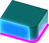
When cleared, you can select:
|
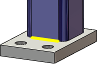
Selection
|
Applies the weld bead to the selected face or edge.
|
|
 |
|
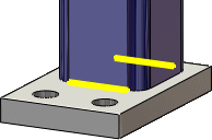
Both sides
|
Applies the weld bead to the selected face or edge and to the opposite face or edge.
|
|
 |
|
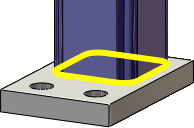
All around
|
Applies the weld bead to the selected face or edge and to all adjacent faces and edges.
|
|
 |
|
| |
Define Weld Symbol |
Opens the Weld Symbol dialog box so you can define the weld symbol settings. The weld symbol is attached to the active weld bead. |
From/To Length
You can use the settings below or use the handles in the graphics area to manipulate the weld bead.
| |
Start point |
Lets you define where to start the weld bead from the first end. |
 |
Reverse Direction |
Starts the weld bead in from the opposite end. |
| |
Weld length |
Sets the length of the weld bead. |
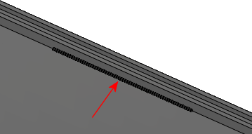 |
| Weld bead defined with a Start point and Weld length |
Intermittent Weld
| Gap and weld length |
Sets the Weld length and Gap for intermittent weld beads. |
| Pitch and weld length |
Sets the Weld length and Pitch for intermittent weld beads. Pitch is defined as the weld length plus the gap. It is calculated from the center of one weld bead to the center of the next weld bead. |
| Staggered |
Available for weld beads set to Both sides. The weld beads alternate positioning on either side of the bodies to weld. 
|