You can insert a tooling split to create the core and cavity blocks for a mold.
To create a tooling split, the part must have at least three surface bodies in the Surface Bodies  folder: a core surface body, a cavity surface body, and a parting surface body. You can create a mold from a tooling split for multiple parts, or for multiple instances of the same part.
To help prevent the core and cavity blocks from shifting, you can add an interlock surface along the perimeter of parting surfaces prior to inserting a tooling split in a mold part. You can also create the interlock surface automatically when you insert the tooling split. To close holes in a molded part, you can add shut off surfaces.
If you do not include the surface bodies with the mold part in advance, you can include a collection of separate surfaces that the tooling split command can automatically knit together.
- Open a part containing a core surface body, a cavity surface body, and a parting surface body.
- Select a face or plane that is perpendicular to the direction of pull.
The selected face or plane is used to define a sketch outline that splits the core and cavity segments.

- Click Tooling Split
 (Mold Tools toolbar).
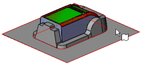
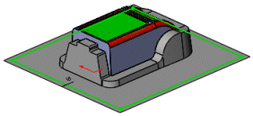
- In the sketch, create a rectangle that extends beyond the model edge, but is within the parting surface boundaries, dimensioning it as required.

- Close the sketch.
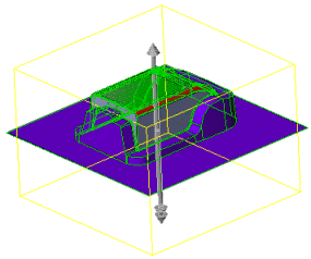
The core, cavity, and parting surface bodies appear in the PropertyManager.
- Under Block Size, enter the value for Depth in Direction 1
 and Depth in Direction 2
  .
.
- To help prevent the core and cavity blocks from shifting, select Interlock Surface.
An interlock surface is created along the perimeter of the parting surfaces.
- Set a value for Draft Angle
 .
.
With most models, manually creating an interlock surface provides better control than relying on automatic creation. You can manually start to add an interlock surface to the parting surface of a mold part with the
Ruled Surface 
tool (Mold Tools toolbar), and complete the interlock surface with other surface modeling tools.
- Click
 .
.You can use
Move/Copy Bodies 
(Features toolbar) to separate the tooling bodies to facilitate viewing them.
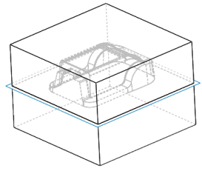
The core and cavity bodies appear.
| Tooling Split Preview |
Tooling Split Applied |
|---|
 |
 |