Parts with conical faces can also be made of sheet metal.
To create a sheet metal part with conical faces:
- Create a thin feature part with one or more conical faces:
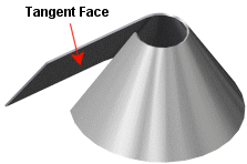
| Any adjacent planar and conical faces must be tangent. |
 |
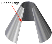
| At least one end face of any conical face must have at least one linear edge. |
 |
- Click Insert Bends
 or .
or .The Bends PropertyManager appears.
- Under Bend Parameters:
- Do one of the following:
- Select a linear edge on an end face of a conical face as the fixed edge.
- Select a planar face tangent to the conical face as the fixed face.
The fixed edge remains in place when the part is flattened. The name of the edge is displayed in the Fixed Face or Edge  box.
box.
- Set the Bend Radius
 .
.
- Select Ignore beveled faces to exclude chamfers from being converted into sheet metal bends.
-
Under Bend Allowance, select from the following bend allowance options: Bend Table, K-Factor, Bend Allowance, Bend Deduction or Bend Calculation.
If creating a sheet metal part with one or more conical faces, you must select
K-Factor as the type of bend allowance.

- If you selected K-Factor, Bend Allowance, or Bend Deduction, enter a value.
- If you selected Bend Table or Bend Calculation, select a table from the list, or click Browse to browse to a table.
-
If you want relief cuts added automatically, select the Auto Relief check box, then choose the type of relief cut. If you choose Rectangular or Obround, then you must specify a Relief Ratio.
The options and values you specify for bend radius, bend allowance, and auto relief are shown as the default settings for the next new sheet metal part that you create.
-
Click
 .
.
Only parts with exact analytic conical faces can be unfolded. Oblong or non-right angle cones are not supported. As a test, try to insert an axis on the conical face. If you can insert an axis, the model is an exact cone. If you cannot insert an axis, then the model is not an exact cone and cannot be unfolded. However, sheet metal parts created with the Lofted Bends feature avoid this limitation and unfold appropriately.