Hide Table of Contents

Solid Mesh Manual (Quality) PropertyManager

After you create a solid mesh with the Manual method, you can inspect the quality of the mesh.

To open the Solid Mesh - Manual (Quality) PropertyManager:

  1. Create a solid mesh with the manual method.
  2. You can access mesh quality and mesh editing tools at the last step of the mesh creating process.

Mesh Editing Tools

Solid Mesh Quality Creates mesh quality plots. Select one of the following:

Aspect Ratio

Displays a mesh quality plot showing the aspect ratio for each element. By increasing the Minimum Value, you can isolate the bad quality elements.

The aspect ratio is defined as the ratio of the circumscribed circle versus the inscribed circle of the element.

EquiAngleSkew

equiangle skew =
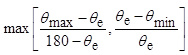
  • θmax = largest angle of element
  • θmin = smallest angle of element
  • θe = 60º for tetrahedra elements, 90º for hexahedra elements.
Displays a mesh quality plot showing the equiangle skew angle for each element.

Twist

A square face is split into two triangles. The angle of normal vectors from the two triangles is the angle of twist.

Maximum Value

Sets the maximum value of the mesh quality parameter shown on the plot.

Minimum Value

Sets the minimum value of the mesh quality parameter shown on the plot.

Extract Surface Mesh Extracts and saves the existing surface mesh data so you don't have to restart the process of creating a surface mesh.
Subdivide Element Refines the local mesh to capture features more accurately.
Auto Adapt Skin Hex Captures edge curves more accurately by adding more hexahedra elements. Elements that do not touch the curves are removed automatically.

Mesh Refine Automatically refines the mesh.

Section Clipping Settings

Creates a cross-section of the mesh to visualize internal (hidden) elements.
+ X Controls the cross-section boundary along the +X axis.
- X Controls the cross-section boundary along the -X axis.
+ Y Controls the cross-section boundary along the +Y axis.
- Y Controls the cross-section boundary along the -Y axis.
+ Z Controls the cross-section boundary along the +Z axis.
- Z Controls the cross-section boundary along the -Z axis.
Reset Resets the cross-section display to the default settings.


Provide feedback on this topic

SOLIDWORKS welcomes your feedback concerning the presentation, accuracy, and thoroughness of the documentation. Use the form below to send your comments and suggestions about this topic directly to our documentation team. The documentation team cannot answer technical support questions. Click here for information about technical support.

* Required

 
*Email:  
Subject:   Feedback on Help Topics
Page:   Solid Mesh Manual (Quality) PropertyManager
*Comment:  
*   I acknowledge I have read and I hereby accept the privacy policy under which my Personal Data will be used by Dassault Systèmes

Print Topic

Select the scope of content to print:

x

We have detected you are using a browser version older than Internet Explorer 7. For optimized display, we suggest upgrading your browser to Internet Explorer 7 or newer.

 Never show this message again
x

Web Help Content Version: SOLIDWORKS Plastics 2017 SP05

To disable Web help from within SOLIDWORKS and use local help instead, click Help > Use SOLIDWORKS Web Help.

To report problems encountered with the Web help interface and search, contact your local support representative. To provide feedback on individual help topics, use the “Feedback on this topic” link on the individual topic page.