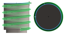
You can use options in the Thread
tool to create helical threads on cylindrical bodies. You need to work carefully as the
interaction of these options sometimes causes subtle errors.
Follow these guidelines to avoid errors.
Create only one vertical centerline that starts from the origin.
SOLIDWORKS uses only one vertical centerline to define the pitch of the thread,
and ignores others. If you draw more than one centerline, you might not be sure
which one is being used.
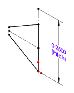
Make sure the centerline is taller than the profile.
Make sure that the centerline is taller than the profile. The height of the pitch
must be greater than the profile between the revolutions. If it is not, revolutions
might intersect with each other.
Pitches are defined differently in inches and metric units.
When you define threads in inches, pitches are defined in terms of revolutions per unit of measure (for example, threads per inch).
When you define threads in metric units, pitches are defined in terms of units of measure per revolution (for example, millimeters per thread).
If you don’t create a centerline, SOLIDWORKS assumes a pitch of one revolution per model unit length (such as, one thread per inch or one millimeter per thread).
Create only one closed contour in a sketch.
SOLIDWORKS can only use one closed contour to define a thread. Creating more than one closed contour in a sketch causes an error.
 |
 |
| One closed contour allowed |
Multiple contours are invalid |
SOLIDWORKS uses only one active sketch in a configuration.
SOLIDWORKS uses the first active sketch and ignores any others. Suppress all of
the sketches but one, so you are sure which one SOLIDWORKS is using to create the
thread.
Take care if you override the default diameter and pitch.
The Thread PropertyManager lets you override the default diameter and pitch. Make
sure that your changes do not create an error, for example, by defining a diameter
for the thread that is inconsistent with the diameter of the cylinder. If you make a
mistake, you can return the diameter and pitch to the default values by using the
pitch override controls.
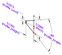
Do not assume too much from a profile name.
Profile names are representative of the profile shape, but not necessarily of the
geometry they create. Do not assume that a profile name indicates the final geometry
of the thread.
Use Library Feature Parts to create profiles.
When you create a profile from scratch, start with the Library Feature Part
methods or a profile provided with the SOLIDWORKS software.
The default directory for storing thread profiles is C:\ProgramData\SolidWorks\SOLIDWORKS YYYY\Thread Profiles.
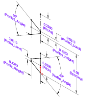
Take care with spatial relationships, especially cut and offset.
Do not change profiles in ways that make the thread inconsistent with the
underlying shape. For example, you might have a profile with a cut thread that works
well on shafts, but not on holes, so you might need to change to extrude for a hole.
Or, you might have a profile that works, but that is offset just far enough to lose
contact with the underlying shaft. If you receive an error after changing the
offset, reverse the change and try a smaller value for the offset.
 |
 |
| In context |
Out of context |