Hole Alignment PropertyManager
|
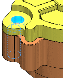
Hole Alignment
checks assemblies for misaligned holes.
To find misaligned holes:
Click Hole Alignment  (Assembly
toolbar) or Tools, Hole
Alignment. (Assembly
toolbar) or Tools, Hole
Alignment. In the
PropertyManager, set options and settings described below. Under Selected Components, click Calculate.
 Hole Alignment
is feature-based. Alignment is checked for Hole
Wizard holes, simple holes, and cylindrical cut features. Hole Alignment does not recognize holes
in derived, mirrored, or imported bodies, or multi-boundary extrudes.
See Unsupported
Hole Types for more information on hole recognition. Hole Alignment
is feature-based. Alignment is checked for Hole
Wizard holes, simple holes, and cylindrical cut features. Hole Alignment does not recognize holes
in derived, mirrored, or imported bodies, or multi-boundary extrudes.
See Unsupported
Hole Types for more information on hole recognition.
|
|
Selected Components
Components to Check. Displays components
selected to check for hole alignment. By default, the top-level assembly
appears unless you pre-select other components. When you check an assembly
for hole alignment, all of its components are checked. If you select two
or more components, only the misalignments between holes in the selected
components are reported.
Hole center deviation. Specifies the
maximum distance between centers for sets of holes to check. For example,
if you specify 1.00mm, then sets
of holes whose centers are within 1.00mm of each other, but not aligned,
are listed under Results.
Calculate. Click to check for hole alignment.
Results
Displays the detected misalignments and reports the maximum deviation
between centers for each set of misaligned holes. You can:
Select items to highlight them in the graphics
area.
Expand items to list the individual holes involved
in the misalignment.
Right-click items and select Zoom
to selection.
If Hole
Alignment recognizes some holes in a part, but detects that it
cannot analyze a portion of the part, it lists the part in a folder named
Partially Analyzed Components
in Results. For example, if you
create a part by mirroring a body that contains Hole
Wizard holes, Hole Alignment
recognizes that the part contains holes, but cannot perform the analysis
because the part contains a mirrored body. You should manually examine
the part and related components for misaligned holes.
Related Topics
Interference
Detection