Expand IntroductionIntroduction
Expand AdministrationAdministration
Expand User InterfaceUser Interface
Expand SolidWorks FundamentalsSolidWorks Fundamentals
Expand Moving from 2D to 3DMoving from 2D to 3D
Expand AssembliesAssemblies
Expand CircuitWorksCircuitWorks
Expand ConfigurationsConfigurations
Expand Design CheckerDesign Checker
Expand Design Studies in SolidWorksDesign Studies in SolidWorks
Collapse Drawings and DetailingDrawings and Detailing
Expand Detailing OverviewDetailing Overview
Expand AnnotationsAnnotations
Expand TablesTables
Expand Bill of Materials (BOM)Bill of Materials (BOM)
Expand Table Columns and RowsTable Columns and Rows
Adding Symbol Text to BOM or Table Cells
Expanding Tables
Expand Equations in TablesEquations in Tables
Expand Drafting StandardsDrafting Standards
Expand Print SettingsPrint Settings
Collapse DrawingsDrawings
Drawings Overview
Expand Getting Started in DrawingsGetting Started in Drawings
Expand Types of Drawing DocumentsTypes of Drawing Documents
Expand Standard Drawing ViewsStandard Drawing Views
Expand Derived Drawing ViewsDerived Drawing Views
Expand Drawing View Alignment and DisplayDrawing View Alignment and Display
Expand Drawing ToolsDrawing Tools
Expand Drawing OutputsDrawing Outputs
Expand Title Block ManagementTitle Block Management
Expand Print OptionsPrint Options
Collapse Dimensions in DrawingsDimensions in Drawings
Dimensions Overview
Inserting Dimensions into Drawings
Dimension Type
Dimensions Options
Aligning Dimensions and Notes
Dimension Alignment: Parallel/Concentric
Dimension Alignment: Collinear/Radial
Rapid Dimension
Autodimension
DimXpert
Parallel Dimensions
Reference Dimensions
Baseline Dimensions
Expand Ordinate DimensionsOrdinate Dimensions
Chamfer Dimensions
Expand Tolerance and PrecisionTolerance and Precision
Moving and Copying Dimensions
Modifying Dimensions
Deleting Dimensions
Expand Dimension PaletteDimension Palette
Extension Lines
Attaching Dimension Extension Lines
Hide/Show Dimensions
Dimensioning to Midpoints
Using Snap Options to Move Dimension Extension Lines
Jogging Extension Lines
Creating Jogs in Dimension Extension Lines
Multiple Jogs for Dimensions and Callouts
Expand DFMXpressDFMXpress
Expand DriveWorksXpressDriveWorksXpress
Expand FloXpressFloXpress
Expand Import and ExportImport and Export
Expand Large Scale DesignLarge Scale Design
Expand Model DisplayModel Display
Expand Mold DesignMold Design
Expand Motion StudiesMotion Studies
Expand Parts and FeaturesParts and Features
Expand RoutingRouting
Expand Sheet MetalSheet Metal
Expand SimulationSimulation
Expand SimulationXpressSimulationXpress
Expand SketchingSketching
Expand Sustainability ProductsSustainability Products
Expand SolidWorks UtilitiesSolidWorks Utilities
Expand TolerancingTolerancing
Expand ToolboxToolbox
Expand WeldmentsWeldments
Expand Workgroup PDMWorkgroup PDM
Expand TroubleshootingTroubleshooting
Expand GlossaryGlossary
Hide Table of Contents

Align Parallel/Concentric

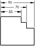
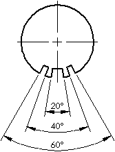
In a drawing, you can align selected linear, radial, or angular dimensions with uniform spacing. Align Parallel/Concentric is used to "stack" and "space" dimensions. The selected dimensions must be of the same type.

To align and group parallel dimensions:

  1. In a drawing, hold Ctrl and select two or more dimensions that you want to align. You can also select the group of dimensions by holding the left mouse button and dragging a box around the dimensions.

  2. Click Align Parallel/Concentric on the Align toolbar, or click Tools, Dimensions, Align Parallel/Concentric.

    The dimensions are arranged with a uniform distance between the arrows. They also are grouped, and retain the parallel spacing when moved.

Aligned Parallel

Aligned Concentric

To specify the distance between dimensions:

  1. Click Tools, Options, Document Properties, Dimensions.

  2. Under Offset distances, specify a value for From last dimension (B) (the distance between dimensions as shown).

  1. Click OK.

To highlight dimensions that are aligned to one another:

Right-click a dimension that was created with Align Parallel/Concentric and click Show Alignment.

Dimensions that are aligned are marked with blue dots.

To remove a dimension from a set of aligned dimensions:

Right-click a dimension that was created with Align Parallel/Concentric and click Break Alignment.

Related Topics

Align Toolbar

Aligning Dimensions and Notes

Ordinate dimensions


Provide feedback on this topic

SOLIDWORKS welcomes your feedback concerning the presentation, accuracy, and thoroughness of the documentation. Use the form below to send your comments and suggestions about this topic directly to our documentation team. The documentation team cannot answer technical support questions. Click here for information about technical support.

* Required

 
*Email:  
Subject:   Feedback on Help Topics
Page:   Align Dimensions Parallel/Concentric
*Comment:  
*   I acknowledge I have read and I hereby accept the privacy policy under which my Personal Data will be used by Dassault Systèmes

Print Topic

Select the scope of content to print:


x

We have detected you are using a browser version older than Internet Explorer 7. For optimized display, we suggest upgrading your browser to Internet Explorer 7 or newer.

 Never show this message again
x

Web Help Content Version: SOLIDWORKS 2011 SP05

To disable Web help from within SOLIDWORKS and use local help instead, click Help > Use SOLIDWORKS Web Help.

To report problems encountered with the Web help interface and search, contact your local support representative. To provide feedback on individual help topics, use the “Feedback on this topic” link on the individual topic page.