Sheet Metal PropertyManagers
Sheet metal PropertyManagers help you create and modify sheet metal parts:
|

|
Sheet-Metal contains the definition of the sheet metal part. This feature stores the default bend parameter information (such as thickness, bend radius, bend allowance, auto relief ratio, and fixed entity) for the entire part.
|
|

|
Flatten-Bends represents the flattened part. This feature contains information related to the conversion of sharp and filleted corners into bends.
Each bend generated from the model is listed as a separate feature under Flatten-Bends. Bends generated from filleted corners, cylindrical faces, and conical faces are listed as RoundBends; bends generated from sharp corners are listed as SharpBends.
The Sharp-Sketch listed under Flatten-Bends is the sketch that contains the bend lines of all sharp and round bends generated by the system. This sketch cannot be edited but can be hidden or shown.
See Flattening Sheet Metal Bends.
|
|

|
Process-Bends represents the transformation of the flattened part into the finished, formed part.
Bends created from bend lines specified in the flattened part are listed under this feature. Flat-Sketch, listed under Process-Bends, is a placeholder for these bend lines. This sketch can be edited, hidden, or shown.
Features listed after the Process-Bends icon in the FeatureManager design tree do not appear in the bent view of the part.
|
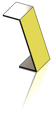
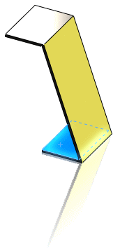
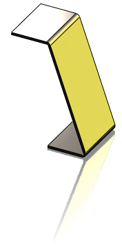
The Bends PropertyManager allows you to convert a shelled part to a sheet metal part. Requirements include:
-
Solid body
-
Uniform thickness
-
Thin feature
|

|
Alternatively, you can create a part directly out of sheet metal with a Base-Flange or by using Convert to Sheet Metal.
To use the Bends PropertyManager to convert a part to sheet metal:
-
Click Insert Bends  (Sheet Metal toolbar) or click Insert, Sheet Metal, Bends.

-
Under Bend Parameters, do the following:
 If the part does not include a planar face, then you can select a
linear edge
.
-
Under Bend Allowance, select from the following options:
,
, Bend Allowance
,
, or Bend Calculation
.
-
If you selected K-Factor, Bend Allowance, or Bend Deduction, type a value.
-
If you want relief cuts added automatically, select the
check box, then select the type of relief cut. If you select Rectangular or Obround, then you must specify a Relief Ratio.
-
If desired, select an edge to rip under Rip Parameters  , and do the following:
-
Click Change Direction if you want to reverse the direction of the rip.
-
In the Rip Gap  box, set a value if you want to set a gap distance.
-
Click OK  .
.
