Relative to Model View
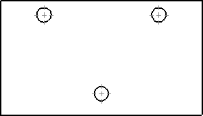
A Relative to Model View is an orthographic (front, right, left, top, bottom, and back) view defined by two orthogonal faces or planes in the model and the specification of their respective orientations. You can use this view type to set the first orthographic view in a drawing to a view different than the default.
You can then create additional orthographic views with the Projected View tool.
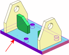
For standard parts and assemblies, the entire part or assembly is shown in the resulting relative view. For multibody parts, (such as weldments), only the selected body is used.
To insert a relative view:
-
Click Relative View  on the Drawing toolbar, or click Insert, Drawing View, Relative To Model. The pointer changes to
  .
.
-
Switch to a model that is open in another window, or right-click in the graphics area and select Insert From File to open a model.
-
In the PropertyManager
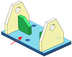
, under Orientation, First, select an orientation (Front, Top, Left, and so on), and select the face or plane for that orientation in the drawing view.

-
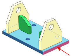
Under Orientation, Second, select another orientation, orthogonal to the first, and select another face or plane for that orientation in the drawing view.

-
If using a multibody part, in the PropertyManager, make selections under Scope.

-
Click OK  and return to the drawing document. The pointer changes to
  .
.
-
In the PropertyManager, select properties then click in the graphics area to place the view.

-
Click OK  .
.
 If the angle of the face in the model changes, the views update to maintain the orientation as originally specified.