Expand IntroductionIntroduction
Expand AdministrationAdministration
Expand User InterfaceUser Interface
Expand SOLIDWORKS FundamentalsSOLIDWORKS Fundamentals
Expand Moving from 2D to 3DMoving from 2D to 3D
Collapse AssembliesAssemblies
Expand The FeatureManager Design Tree in an AssemblyThe FeatureManager Design Tree in an Assembly
Expand Basic Component OperationsBasic Component Operations
Design Methods (Bottom-up and Top-down Design)
Expand Top-Down DesignTop-Down Design
Collapse MatesMates
FAQ Mates
Best Practices for Mates
Expand Basic Mate OperationsBasic Mate Operations
Expand Mate PropertyManagerMate PropertyManager
Mate Icons in the FeatureManager Design Tree
Standard Mates by Entity
Preventing Rotation in Concentric Mates
Expand Types of MatesTypes of Mates
Spherical and Curvilinear Mates
Expand SmartMatesSmartMates
Expand Visualizing Mate SystemsVisualizing Mate Systems
Collapse Solving Mate ProblemsSolving Mate Problems
Mate Errors
Expand MateXpertMateXpert
Techniques for Fixing Mate Problems
Collapse Mate Error ExamplesMate Error Examples
Example: Conflicting Mates
Example: Conflicts Between Mates and In-context Features
Example: Design Errors and Mating
Example: Concentric Mate Error
Example: Fixing Redundant Distance Mates
Example: Mates to Dangling Geometry
Mated Entities PropertyManager
Missing Entities Pop-up Toolbar
Expand SubassembliesSubassemblies
Expand Controlling Display and Appearance in AssembliesControlling Display and Appearance in Assemblies
Expand External FilesExternal Files
Expand Detecting ProblemsDetecting Problems
Expand Exploded Views in AssembliesExploded Views in Assemblies
Expand Other Assembly TechniquesOther Assembly Techniques
Expand Large AssembliesLarge Assemblies
Expand CircuitWorksCircuitWorks
Expand ConfigurationsConfigurations
Expand SOLIDWORKS CostingSOLIDWORKS Costing
Expand Design CheckerDesign Checker
Expand Design Studies in SOLIDWORKSDesign Studies in SOLIDWORKS
Expand Detailing and DrawingsDetailing and Drawings
Expand DFMXpressDFMXpress
Expand DriveWorksXpressDriveWorksXpress
Expand FloXpressFloXpress
Expand SLDXML Data ExchangeSLDXML Data Exchange
Expand Import and ExportImport and Export
Expand Model DisplayModel Display
Expand Mold DesignMold Design
Expand Motion StudiesMotion Studies
Expand Parts and FeaturesParts and Features
Expand RoutingRouting
Expand Sheet MetalSheet Metal
Expand SimulationSimulation
Expand SimulationXpressSimulationXpress
Expand SketchingSketching
Expand Sustainability ProductsSustainability Products
Expand SOLIDWORKS MBDSOLIDWORKS MBD
Expand SOLIDWORKS UtilitiesSOLIDWORKS Utilities
Expand TolerancingTolerancing
Expand TolAnalystTolAnalyst
Expand ToolboxToolbox
Expand WeldmentsWeldments
Expand Workgroup PDMWorkgroup PDM
Expand TroubleshootingTroubleshooting
Glossary
Hide Table of Contents

Example: Conflicts Between Mates and In-context Features

Mating conflicts happen when you create in-context sketch relations and then create distance mates using the components and entities that use the sketch relations.

The conflict happens because the distance mate tries to pull the faces apart, while the in-context sketch relations try to pull the faces together. These mate conflicts cause problems such as slower rebuilds, "growing" parts, "walking" origins, and incorrect drawing views.
Such conflicts happen only if the mate conflicts with an existing in-context relation. You can create parts in the context of an assembly without referencing other geometry. These types of parts do not cause a conflict if you delete the inplace mate.

Example

  1. Gray block is fixed in an assembly.

  2. Insert a new part and sketch a rectangle.

  3. Create an in-context collinear relation between the sketch line and the edge of the fixed gray block.

  4. Extrude the sketch, then assign a distance mate (for example 80 mm) between the two faces shown.

    The software first applies the distance mate, which pushes the two components apart.
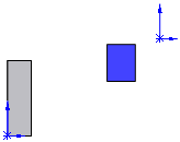
    Then the software rebuilds the components, and the in-context collinear relation pulls the edge of the blue block back to the edge of the gray block. This causes the block to "grow."
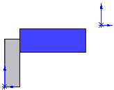
    The next time the mate solves, the blue block gets pushed farther away, and then the edge gets pulled back to the gray block, increasing the size of the blue block again.

    Each time you rebuild the assembly, the blue block continues to grow.

    MateXpert lists the distance mate as not satisfied. The Mates folder shows a red mate error symbol fm_whats_wrong_x.png and the What's Wrong dialog explains the conflict: the actual distance is 0 (per the in-context sketch relation), while the desired distance is 80 (per the distance mate).


Provide feedback on this topic

SOLIDWORKS welcomes your feedback concerning the presentation, accuracy, and thoroughness of the documentation. Use the form below to send your comments and suggestions about this topic directly to our documentation team. The documentation team cannot answer technical support questions. Click here for information about technical support.

* Required

 
*Email:  
Subject:   Feedback on Help Topics
Page:   Example: Conflicts Between Mates and In-context Features
*Comment:  
*   I acknowledge I have read and I hereby accept the privacy policy under which my Personal Data will be used by Dassault Systèmes

Print Topic

Select the scope of content to print:


x

We have detected you are using a browser version older than Internet Explorer 7. For optimized display, we suggest upgrading your browser to Internet Explorer 7 or newer.

 Never show this message again
x

Web Help Content Version: SOLIDWORKS 2015 SP05

To disable Web help from within SOLIDWORKS and use local help instead, click Help > Use SOLIDWORKS Web Help.

To report problems encountered with the Web help interface and search, contact your local support representative. To provide feedback on individual help topics, use the “Feedback on this topic” link on the individual topic page.