The orthotropic material directions throughout a component are defined based on the selected reference geometry selected.
If a part is manufactured such that you cannot define a common reference geometry for the whole component, then you should model it as different parts in order to define orthotropic directions properly.
For example, consider the part shown in the figure:
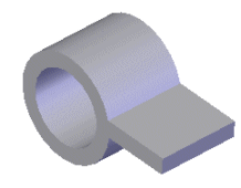
You need to model this part as two parts: the cylinder and the planar sheet. You can then use a plane as the reference geometry for defining the orthotropic material directions for the planar sheet and the axis of the cylinder as the reference geometry for the cylinder.
 |
 |
| The radial (X), tangential (Y), and axial directions (Z) for an orthotropic material when an axis is used as a reference geometry.
|
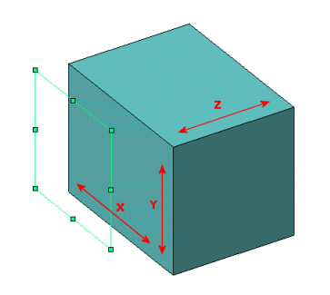
The X, Y, and Z directions for an orthotropic material when a plane is used as a reference geometry.
|