Use the axisymmetric option when the geometry, material properties, loads, fixtures, and contact conditions have a rotational symmetry about an axis. You can model any cross section about the axis of revolution. If you use multiple bodies, they have to be symmetric about the same axis.
When defining orthotropic material properties for the 2D sections, the X, Y, and Z directions represent the cylindrical coordinates. The material properties are the same along the circumferential direction.
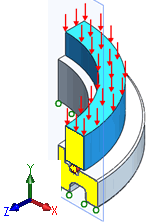
The figure shows an o-ring pressed into a groove by a top plate.

You can create the 2D section in yellow and define contact conditions between the outer edges of the top plate, o-ring, and the groove. You can then apply the load to an edge of the top plate and restrain the bottom plate.
On the section plane, if you denote the X, Y, and Z directions as r, y, and θ respectively, the following simplifications are applied for simulation results.
| Displacement |
uθ = 0, where uθ is the displacement along the circumferential direction. |
| Stress |
To maintain symmetry about Y axis, τrθ = 0 and τθy = 0, where τ represents shear stress components. |
| Strain |
To maintain symmetry about Y axis, γrθ = 0 and γθy = 0, where γ represents shear strain components. |