If you have components with two holes, you can mate those components even
when the holes are not the same distance
apart.
You can align the mate to resolve exactly with either the first or
the second concentric mate and apply the offset to the concentric mate that is not
aligned. Or you can apply the offset equally to both sets of mated holes. You can
also specify an allowed tolerance, beyond which the misaligned mates over define the
assembly and display an error.
To allow misaligned mates:
-
In an assembly, add a concentric mate between the first pair of
holes.
-
Add a concentric mate between the second pair of holes.
-
In the dialog box, click Create this mate using
misalignment options.
If you do not see Create this mate using
misalignment options in the dialog box, go to and select the Allow creation of misaligned
mates option.
-
In the PropertyManager, select Align Linked
mate for the misalignment type.
-
Click
 .
.
In the graphics area, you can click Section
View
 (Heads-up View toolbar)
and zoom to view the edges of each mate. Notice the gap between the surface
and edge in the second mate.
(Heads-up View toolbar)
and zoom to view the edges of each mate. Notice the gap between the surface
and edge in the second mate.
| First mate solves exactly |
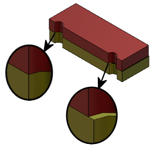 |
| Second mate displays misalignment
distance |
In the FeatureManager design tree, the two concentric mates show in
a Misaligned folder

under the Mates
folder.