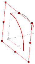
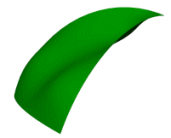
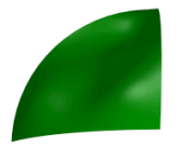
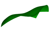
This model uses sketches as patch boundaries for the filled surface. To help shape the patch, it also uses sketch points and a spline as constraint curves.
Creating a filled surface using constraint curves:
-
Sketch1 - Sketch an arc on Plane1 (Front) and dimension.
-
Sketch2 - Sketch an arc on Plane3 (Right), dimension, and add the necessary relations.
 |
 |
| Sketch1 |
Sketch2
|
- Sketch3 - Sketch an arc to connect Sketch1 and Sketch2 on Plane2 (Top). Dimension and add the necessary relations.
-
Create Plane4 (at angle to Plane1) and add sketch points (Sketch4), as shown, to use as constraint curves.
- Create Plane5 (offset from Plane2) and sketch spline (Sketch5), as shown, to use as a constraint curve.
- Click Filled Surface
 on the Surfaces toolbar, or .
- In the graphics area, under Patch Boundary, select the edges created by Sketch1, Sketch2, and Sketch3.
The edges, along with the curvature type are listed under
Patch Boundaries 
.
The curvature control defaults to Contact because only contact surfaces are eligible with sketch boundaries.
- Under Constraint Curves, select Sketch4 and Sketch5 in the graphics area for Constraint Curves
 .
.
- Click OK
 .
.
 |
 |
 |
| Three views of the industrial design example with filled surface applied
|